Overview of Using Java as an Abstract Modeling and Specification Language
This document summarizes the Java-based modeling and specification language, we'll use in CSC 308. The base Java language we'll use for modeling is 100% standard Java syntax, as defined in the third edition of the Java Language Specification, available at http://docs.oracle.com/javase/specs We will also use the formal specification annotations of the Java Modeling Language (JML), as defined in the documentation at the JML website and the www.eecs.ucf.edu/~leavens/JML/documentation.shtml
This handout covers the base Java modeling language. A companion handout will cover the formal specification aspects of JML. The "base" modeling language refers to the proper subset of standard Java that we will use for high-level program modeling.
Java as a modeling language has features found in other modeling and specification languages. The basic features for specifying objects and operations are found in a long historical line of modeling languages. These include SADT (Structured Analysis and Design Technique) [Ross 77], PSL (Problem Statement Language) [Teichroew 77], RMF (Requirements Modeling Framework) [Greenspan 82], OMT (Object Modeling Technique) [Rumbaugh 91], and most recently UML (Unified Modeling Language) [Rumbaugh 99].
The purpose of Java as a modeling language is to describe precisely the
external structure of the objects and operations in a software system. While
languages such as UML have useful features for structuring a specification,
they are not fully formal. The Java Modeling Language (JML) includes features
for formal specification, as found in such languages as Larch [Guttag 85], OBJ
[Goguen 88], and OCL (Object Constraint Language). A JML specification is
typically developed in sequences of refinements, where definitions of objects
and operations are gradually made more formal.
2. Underlying Principles
All modeling languages share some common underlying principles. The principles are:
An object is specified as a Java class, of the form
/*
 * Object description, in a Javdoc-style comment -- at least two initial *'s.
 */
abstract class <name> extends ... {
    // data fields
    // abstract method signatures
}
/**
 * A calendar is composed of zero or more scheduled items.
 */
abstract class Calendar {
    Collection < ScheduledItem > items;
}

/**
 * A ScheduledItem is the generic definition for the types of items stored in a
 * calendar.  A ScheduledItem has a title, start date, and end date.
 * Extensions of ScheduledItem are Appointments, Meetings, Events, and Tasks.
 */
abstract class ScheduledItem {
    components: Title and StartDate and EndDate;
}
If a model class has no operations, then the abstract keyword can be
omitted from the class declaration. However, it is a good practice
always to include the abstract keyword for classes.
4. Specifying Operations
An operation is specified by its signature only, and its association within a class. For example:
/**
 * A calendar is composed of zero or more scheduled items.
 */
abstract class Calendar {

    /**
      * The scheduleAppointment operation adds the given Appointment to this
      * Calendar.
      */
    abstract void scheduleAppointment(Appointment appointment);

    Collection < ScheduledItem > data;

}
An object or operation specifies a class from which other objects may inherit. This form of inheritance is conceptually the same as in all object-oriented programming languages. For example,
/**
 * An Appointment adds a number of components to a generic ScheduledItem.  The
 * StartTime and Duration indicate when the appointment starts and how long it
 * lasts.  RecurringInfo defines if and how the appointment recurs more than
 * once.  The Location is where it is held.  The AppointmentSecurity indicates
 * who can see that the appointment is scheduled.  Priority is how important
 * the appointment is.  RemindInfo indicates if and how the user is reminded of
 * the appointment.  Details are free form text describing any specific
 * appointment details.
 */
abstract class Appointment extends ScheduledItem {
    Time startTime;
    Duration duration;
    RecurringInfo recurringInfo;
    Location location;
    AppointmentSecurity security;
    AppointmentPriority priority;
    RemindInfo remind;
    Text details;
}

/**
 * Like an Appointment, a Meeting adds components to a generic ScheduledItem.
 * A Meeting differs from an Appointment as follows: (1) Security for an
 * appointment includes a private option that is not available for meetings.
 * (2) Meetings have Attendees and Minutes components, Appointments do not.
 */
abstract class Meeting extends ScheduledItem {
    Time startTime;
    Duration duration;
    RecurringInfo recurringInfo;
    Location location;
    MeetingSecurity meetingSecurity;
    AppointmentPriority priority;
    RemindInfo remindInfo;
    Attendees attendees;
    Text Details;
    Text Minutes;
}
class StaffMeeting extends Meeting { /* ... */}
class UserMeeting extends Meeting { /* ... */}
For large specifications, it can be convenient to organize object and operation definitions into packages. This is done in the standard java syntax, declaring the package in which a class or classes reside in the first line of the Java source file. For example:
package schedule;

abstract class Calendar { /* ... */ }
abstract class ScheduledItem { /* ... */ }
abstract class Appointment extends ScheduledItem { /* ... */ }
abstract class Meeting extends ScheduledItem { /* ... */ }
abstract class StaffMeeting extends Meeting { /* ... */ }
abstract class UserMeeting extends Meeting { /* ... */ }
Models specified in Java can be depicted in tabular and graphical forms. The tabular form is called a "data dictionary", that lists the major attributes of objects and operations. Data dictionaries are a very well established format that have been used in software engineering for many years.
The graphical notation uses concepts from the Unified Modeling Language (UML) and some other commonly used graphical forms. UML is the most recent in a long line of graphical modeling notations that date back as far as the mid-70s with SADT [Ross 77] and PSL/PSA [Teichroew 77]. The development of UML was a collaborative effort of primarily commercial organizations, led by the Rationale Corporation. The goal for UML has been to develop a standard graphical modeling notation. UML is a consolidation of concepts used in earlier notations, in particular the Object Modeling Technique (OMT) [Rumbaugh 91].
UML has a number of features that are not used in the notation described here.
In addition, UML is missing certain features that are convenient for
diagramming abstract models, in particular dataflow diagrams. Where a feature
is available in UML, the same feature is retained here. Where UML is missing a
useful feature, a previously existing standard is used in such a way as not to
conflict with UML features. Also of note are some terminology differences
between the notation presented here and UML. In particular, the terms
"object", "component", and "composition" are used here as they relate to Java.
These terms are used differently in standard UML.
6.1. Data Dictionaries
Data dictionaries are common notation for describing objects. A data
dictionary shows objects, their components, and descriptions. Figure 1 shows
the data dictionary format for the object definitions given as examples in
Sections 2 through 5 above.
|
Object Name |
Components |
Description |
| Appointment |
inherits from ScheduledItem
adds StartTime and Duration and Location and AppointmentSecurity and Priority and RemindInfo and Details |
An Appointment adds a number of components to a generic ScheduledItem. The
StartTime and Duration indicate when the appointment starts and how long it
lasts. The Location is where it is held. The AppointmentSecurity indicates
who can see that the appointment is scheduled. Priority is how important the
appointment is. RemindInfo indicates if and how the user is reminded of the
appointment. Details are free form text describing any specific appointment
details.
|
| Calendar | ScheduledItem* |
A calendar is composed of zero or more scheduled items.
|
| ScheduledItem |
Title and StartDate and EndDate
|
A ScheduledItem is the generic definition for the types of items stored in a
calendar. A ScheduledItem has a title, start date, and end date.
Specializations of ScheduledItem are Appointments, Meetings, Events, and Tasks,
q.q.v.
|
| Meeting |
inherits from ScheduledItem
adds StartTime and Duration and Location and MeetingSecurity and Priority and RemindInfo and Attendees and Details and Minutes |
Like an Appointment, a Meeting adds components to a generic ScheduledItem. A
Meeting differs from an Appointment as follows: (1) Security for an appointment
includes a private option that is not available for meetings. (2) Meetings
have Attendees and Minutes components, Appointments do not.
|
| StaffMeeting |
inherits from Meeting
adds ... |
|
| UserMeeting |
inherits from Meeting
adds ... |
|
Figure 1: Example Data Dictionary.
As commonly used, data dictionaries are typically a less formal notation than a complete language such as Java. Therefore the details of how data dictionaries are used in practice can vary among different authors. In some uses, there is no separate components column, so that everything about the object is described in the prose description column. Also, the exact notation used in components definitions may vary. For example, some authors use "+" instead of "and" for defining composition.
The javadoc tool for Java documentation produces a data dictionary of
sorts. The javadoc has many details that are not typically found in a
data dictionary. In general, data dictionaries are a simple form, intended for
viewing potentially by end users, not just developers. The output of
javadoc is not particularly well suited for viewing by non-
programmers.
6.2. Class Diagrams
A class diagram depicts the composition and inheritance relationships among Java objects. It can also show the operations that are associated with an object, where "associated with" means those operations listed in an object's operations attribute. The elements of a class diagram are the following:
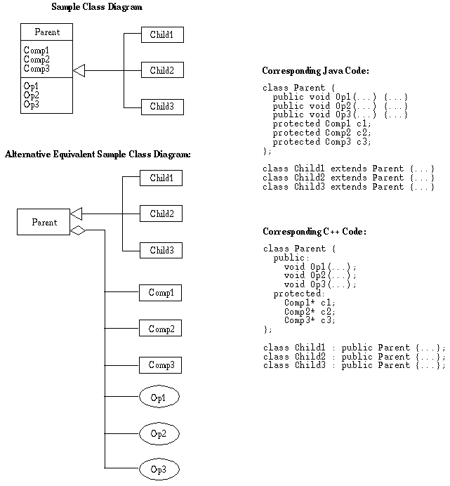
Figure 2 shows the general structure. Two equivalent graphical forms are shown
on the left, with the corresponding textual form on the right.

Figure 2: General Structure of a Class Diagram.
The diagram on the top left of the figure shows components and operations using the three-part box notation. The diagram on the bottom left, labeled "Alternative Equivalent", shows the equivalent relations using the hollow diamond notation. To illustrate how modeling concepts are common in a variety of languages and notations, textual forms are shown in Java and C++, as well as in Java. All five forms in the figure (two diagram forms, three textual forms) have the same abstract meaning.
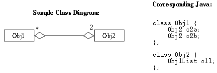
Figure 3 shows the basic form of multiplicity annotations, as well as two-way
containment.

Figure 3: Two-Way Containment in a Class Diagram.
The three-part notation for composition versus the hollow diamond notation are two equivalent forms that have the same meaning. Composition can be shown in either way separately, or with the two forms combined in a single diagram. When the two forms are used together, components should not be repeated. That is, each object component should be shown in the second part of a three-part box or shown as a hollow diamond attachment, but not shown in both ways in the same diagram. A UML convention is to show atomic components in the second part of a three-part box and non-atomic components as hollow-diamond attachments. In Java, atomic components are integer, real, string, boolean, and opaque objects. An opaque object has no components at all, just a name. It is conceptually comparable to an enumeration literal in common programming languages.
Figure 4 shows an example class diagram depicting the object definitions given
as Java examples in Sections 2 through 5 above.

Figure 4: Example class diagram.
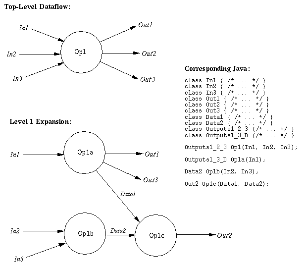
A dataflow diagram depicts the flow of objects between operations in a specification. Elements are:
Figure 5 shows the general structure.

Figure 5: General Structure of a Dataflow Diagram.
A dataflow diagram is only a possible depiction of flow since the
interconnections actually show more information than is in the abstract Java
specification. That is, the specification defines the input and output types
of each operation, but does not require that they be interconnected as shown in
any particular dataflow diagram.
6.4. Package Diagrams
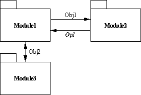
A package diagram is for large-grain modeling, showing the relationship between modules. Elements of a package diagram are the following:
Figure 6 shows the general structure.

Figure 6: General Structure of a Package Diagram.
The interconnection abstractly depicts communication in that the
diagram does not show the details of the communication. For data
communication, the package diagram indicates that one module sends data to
another, without indicating the operation that produces the data. With
functional communication, only the name of the operation is given without
indicating the details of input and output.
7. Conclusion
Java is a formal and mechanically checkable language for requirements modeling and formal specification. It has constructs found in many requirements specification notations, both graphical and textual. Independent of syntactic details, virtually all notations share a common set of underlying principles, most notably object modeling, operation modeling, and hierarchical model decomposition.
[Goguen 88] J. A. Goguen and T. N. Winkler, "Introducing OBJ3", SRI International Technical Report, Palo Alto, CA, August 1988.
[Greenspan 82] S.J. Greenspan, J. Mylopoulos, and A Borgida, "Capturing More World Knowledge in the Requirements Specification", Proceedings of the Sixth International Conference on Software Engineering, 1982.
[Guttag 85] J. Guttag, J. J. Horning and J. M. Wing, "The Larch Family of Specification Languages", IEEE Software, May 1985.
[Rumbaugh 91] J. Rumbaugh, M. Blaha, W. Premerlani, F. Eddy, and W. Lorensen, "Object-Oriented Modeling and Design", Prentice-Hall, 1991.
[Rumbaugh 99] Rumbaugh J., I. Jacobsen, G. Booch, "UML Reference Manual", Addison-Wesley.
[Ross 77] D. T. Ross, "Structured Analysis (SA): A Language for Communicating Ideas", IEEE Transactions on Software Engineering, January 1977.
[Teichroew 77] D. Teichroew and E. A. Hershey III, "PSL/PSA: A Computer-Aided
Technique for Structured Documentation and Analysis of Information
Processing Systems", IEEE Transactions on Software Engineering,
January 1977.