- The point of these notes is to show that among the superficially different notations for modeling expressing software requirements and specifications, there are a handful of common underlying principles that all notations share.
- The languages differ primarily in the degree of formality they require and the notational syntax they use.
-
The underlying principles common to all requirements specification notations
are the following:
- Object/Operation Modeling -- a requirements model is comprised fundamentally of two forms of entity: objects and operations; these entities have well-defined relations to one another.
- Hierarchy -- an important relation between entities of the same type is hierarchy; that is, an entity is composed hierarchically of components, which may in turn be further hierarchically decomposed.
- Input/Output Relationships -- the primary relation between objects and operations is input/output; specifically, operations take objects as inputs and produce objects as outputs.
- Attribute/Value Pairs -- in addition to relations to other entities, an entity may have other general attributes that further describe its properties and characteristics.
- Class/Subclass/Instance Composition -- a secondary form of hierarchical relation is that of class/instance; an entity class defines a generic entity template; an entity subclass or instance specializes the generic class by adding additional attributes.
- Formal language used?
- Textual notation, graphical notation, or both?
- Supports requirements, specification, or both?
-
Centered on?
- Human end user model
- Hardware/software/environment model
- Software model
- Database model
- Formal mathematical model
- Most of the notations are used in the context of a specific requirements analysis and/or specification methodology.
- In 508 terms, each notation has its own particular process in which it is used.
- These notes will focus primarily on the notation, with some secondary discussion of the methodology.
- To a very large extent, the structure of the process follows the structure of the notation.
- In the UI-centered modeling technique we've used in 508, the requirements specification model focuses solely on software functionality.
-
Most requirements languages, including RSL, support modeling of more than just
the software.
- Specifically, a requirements model may include models of the software, hardware, humans, and other environmental components.
- Based on the type of software we are modeling, i.e., software tools with substantial GUI components, we have factored out all model components except the software and its human end users.
-
The decision of how much of a system and its environment to model is based on:
- How much modeling is necessary in order for the analyst to understand the application domain fully.
- How much of the operational system the analyst is required to specify, e.g., is the analyst specifying both hardware and software.
- In a complicated application domain, the analyst may need to formally model more than the software functionality alone in order to gain sufficient understanding of the software requirements, even when only the software ultimately needs to be modeled.
- Synopsis: A non-formal graphical and textual notation, supporting requirements and specification, centered on a hardware/software/environment model.
- Standard reference: DeMarco, Tom, Structured Analysis and System Specification, Yourdon Press, 1978.
-
History:
- Originally, SA was part of the overall Structured Design methodology for overall software development.
- Subsequently, elements of SA have been adopted by various other methodologies, such as OMT.
- By itself, SA has largely been supplanted by OMT and other more recent techniques.
-
Notational elements:
-
Dataflow diagram:

-
Data dictionary:
Datum Name Definition Remarks ... ... ... where the definition is a compositional expression using the following symbols:
Symbol Meaning = is composed of + and () optional {} iteration [] select one of several alternative choices | separates alternative choices in the [] construct @ identifier (key field) for a store -
Process specifications:
- Process specifications written in an informal form of pseudo code, often called a program design language (PDL).
- PDL can be expressed as a subset of an existing programming language, flow- charts, decisions tables, or other comparable notations.
-
Dataflow diagram:
- Synopsis: A potentially formal textual and graphical notation, supporting a narrow range of requirements and specification, centered on a database model.
- Standard reference: Chen, Peter, The Entity- Relationship Model -- Toward a Unified View of Data, ACM transactions on Database Systems, Volume 1, Number 1, March 1976.
-
History:
- As the standard reference implies, ER modeling was intended originally for modeling of data as they would be represented in a computerize relational database.
- The ER notation and/or concepts have subsequently been adopted for use in more general settings, including SA and OMT.
-
Notational elements:
-
Basic relation:

-
Associative-entity relation:
Directional relation:

-
Basic relation:
- Synopsis: a combination of SA and ER.
- Standard reference: Yourdon, Edward, Modern Structured Analysis, Yourdon Press, 1989.
-
Synopsis: A formalized (but not fully formal),
predominantly graphical notation centered on a software model.
- "Booch" is the name of the notation inventor and promoter -- Grady Booch.
- "OMT" stands for "Object Modeling Technique", as described in the 1991 book by James Rumbauch, et al.; it is often called "Rumbaugh Notation".
- "UML" stands for the "Unified Modeling Language, as described in the 1997-1999 UML standard.
-
History:
- Booch began ca. 1985, OMT ca. 1991
- Booch and OMT are widely used in practice today, more in industry than in academia, though academic use is common.
- Given the currently wide use of Booch and OMT, it is expected that UML will be adopted by most of not all of the current Booch and OMT users, plus attract new users due to the unified presentation and potential for standardization.
-
Notational elements:
- We use concrete interface scenarios in place of abstract diagrams as the primary means of model communication with the end user.
- We use the RSL textual notation as the primary means of formal model definition, with diagrams as the secondary notation for conveniences of presentation.
- All forms of sequencing diagrams provided by UML are considered implementation- level in the 508 modeling methodology and are therefore not used. (They will be used next quarter in 509.)
-
For primarily transactional systems, including highly interactive systems such
as Inferno, DFDs are of potentially limited use in requirements modeling, as
the following examples illustrate.
- DFDs are best employed primarily transformational systems, where there is not frequent end-user interaction with a large body of data.
- For this reason, heavily object-oriented modeling techniques, such as UML, do not provide a DFD notation.
- This is not to say that DFDs are not useful in appropriate contexts, just that highly interactive single-user systems are not best modeled with DFDs.
-
Figure 1 shows the top-most level DFD of the Inferno environment
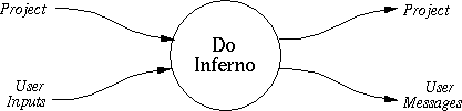
Figure 1: Inferno top-most DFD (a context diagram).
- Such DFDs, consisting of exactly one node, are typically called a context digram.
- One of the problems with such diagrams is they do not necessarily correspond to a level of user interaction that is useful to model (more on this below).
-
Figure 2 shows the top-level expansion DFD for the Inferno environment
- It is based on the top-level commands available in a standard command menu.
- The vertical layout and lack of data dependency between the DFD nodes indicates that the nodes can be executed in any order.
- Since these operations are performed under the control of a single human user, only one operation at a time will execute, although this is dictated by the DFD itself.
- In any DFD, non-data-dependent nodes may execute concurrently.
-
Figure 3 shows an expansion of the File node that appears in the top-level
diagram.
- In general, DFDs can be expanded to any depth by showing the details of a non- atomic operation.
- Depending on the degree of DFD formality employed by a particular methodology, specific rules for DFD leveling can be specified.
-
For example:
- All inputs and outputs at level i must be accounted for at level i+1
- A form of parallel data decomposition may be used, where a composite input object at level i can be automatically decomposed into its components for use as individual inputs at level i+1
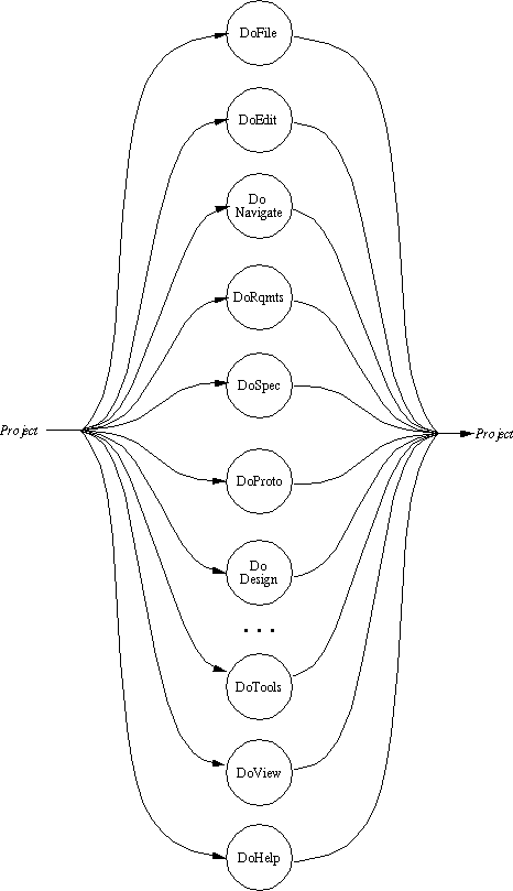
Figure 2: Top-Level Inferno DFD.
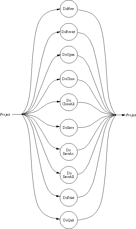
Figure 3: Expansion of File Operation.
-
Figure 4 shows a poorly-conceived expansion of the New operation of
level 2.
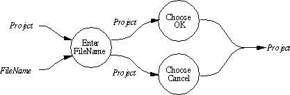
Figure 4: Poorly-conceived expansion of File.New operation.
-
It is poorly-conceived in a number of ways:
- It is programming at the level of GUI interaction, which in our methodology is inappropriate.
- It is unclear what kind of splitting occurs to produce the two outputs of EnterFileName.
- It is similarly unclear what kind of join operations occurs when the separate outputs from ChooseOK and ChooseCancel are combined into a single output.
- This kind of DFD is quite representative of what is produced where there are no formal rules for DFD semantics.
- In almost all uses of DFDs in requirements methodologies, DFD semantics are informal, requiring that users define their own usage rules if they choose.
-
It is poorly-conceived in a number of ways:
-
Here are some questions regarding the use of DFDs, such as those illustrated
above
- What exactly is the valued added of the DFDs, given that we have an RSL or equivalent definition of all of the drawn operations? (Fisher answer: none.)
- Do we even need to define all of the drawn operations; consider in particular all of the operations at level 1? (Fisher answer: no.)
- What are the definitions of the UserInputs and UserOutputs objects defined in the level 0 context diagram? (Answer: the union of all possible user inputs at all levels of operation.) Do we really need to define these objects? (Fisher answer: no.)
- Should UserInputs and UserMessages be shown at levels 2 and 3? (Fisher answer: maybe yes, maybe no, depending on what exactly we're trying to model in the way of user input processing. This kind of answer is clearly problematic if we're hoping for some level of formality in our specification.)
-
Based on the answers to the preceding questions, here is Fisher's view on the
use of DFDs in requirements and specification:
- If there is a demonstrable need to show the details of user operation sequencing, then a DFD can be used.
- If there is a need to understand some details of how a surrounding environment operates, where we are modeling more than software functionality alone, then a DFD can be used.
- In a user-centered methodology where our model focuses on software functionality alone, and the user completely controls the flow of operation execution through a non-model interface, DFDs provide no value added.
-
Figure 5 shows the definition of a process as a collection of zero or more
ProcessSteps (in RSL, obj Process is ProcessStep*).
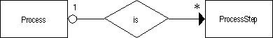
Figure 5: ER definition of Process.
-
Figure 6 shows the definition of a process as a tuple of ProcessStepName,
PreviousStep, etc.(in RSL, obj ProcessStep is ProcessStepName and
PreviousStep and ... ).
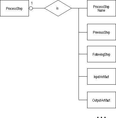
Figure 6: Excerpt of ER definition of ProcessStep.
-
Figure 7 shows the definition of "produces" and "produced-by" relations that
exist between
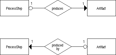
Figure 7: Excerpt of ER definition of produces and produced- by.
- In RSL, such non-standard relations can be specified with user-defined relational attributes.
-
For example, here is the RSL definition for the produces and produced-by
relations:
module ProcessAndArtifactWhichReallyShouldBeInTwoSeparateModules define attribute produces; define attribute produced_by; ... obj ProcessStep is ... produces: Artifact; end; obj Artifact is ... produced_by: ProcessStep; end; -
Note that in RSL there is no specific notation for the multiplicity of
relational attributes, other than '*' meaning zero or more.
- Unbounded multiplicity can be defined by making a list object the value of a relational attribute.
- There is no direct way to specify bounded multiplicity in a relation -- this must be modeled using object components.
-
Figure 8 shows a possible use of associative relation in Inferno
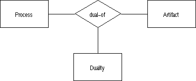
Figure 8: Excerpt of ER definition of produces and produced- by.
-
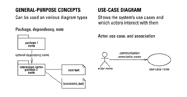
A use case is a statement of required functionality of the form
Actor Action Subject
where- an "Actor" represents a "stimulus" to a system (a.k.a., an input tagged by the agent that provides it)
- an "Action" represents an operation that the system performs
- a "Subject" represents the object acted upon
-
In terms of RSL-style definition, a use case is a single operational scenario
that defines a particular case for the invocation of an operation.
- In this sense, a use case defines all or part of an operation's signature.
- The Actor of a use case may define the agent performing the operation, or the input to the operation, or both.
- The Subject of a use case may define the output of the operation, or the input and output.
- The action is the operation itself
- In many use-case-based methodologies, the use case is type-tagged with the type of its actor, as in hardware, software, or human.
-
Some use case examples and their RSL equivalents (from Texel and Williams,
Use Cases Combined with Booch, OMT, UML, Prentice-Hall, 1997):
Use Case RSL Software Monitors Living_Quarters op Monitor(LivingQuarters)->LivingQuarters) Timer Triggers Living_Quarters_Sensor op TriggerChange(Timer,LivingQuarters)->LivingQuarters Software Lights Window op LightWindow(lq:LivingQuarters)->lq':LivingQuarters
post: if (...) then (lq'.lit = true);
-- alternatively --
op TriggerChange(Timer,lq:LivingQuarters)->
lq':LivingQuarters
post: if (lq.state ...) then (lq'.lit = true)
-
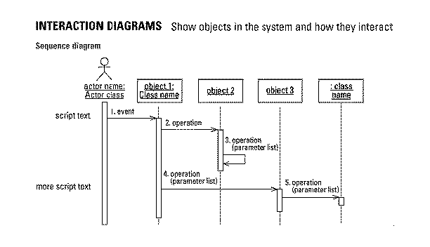
UML provides four object-oriented forms of diagram for defining the flow of
control among operations:
-
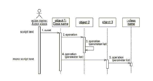
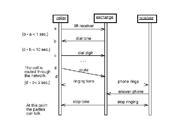
Sequence diagram -- shows time-sequenced message passing between
objects
-
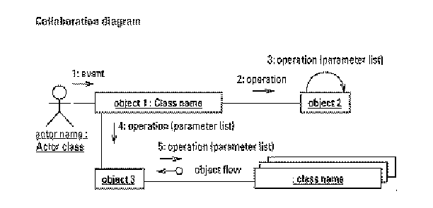
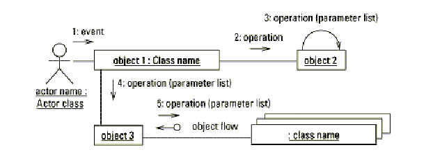
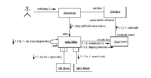
Collaboration diagram -- shows message passing between objects without
explicit time sequencing
-
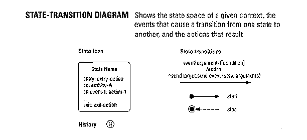
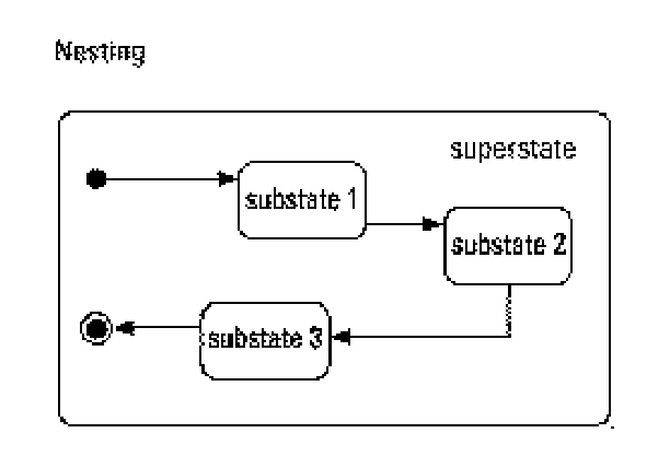
Statechart diagram -- shows the sequences of states an object goes
through in response to received stimuli
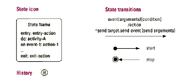
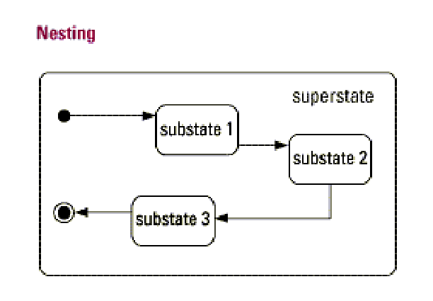
- Activity diagram -- a state machine diagram in which a state represents the activity of performing an operation and transitions are triggered by operation completion.
-
Sequence diagram -- shows time-sequenced message passing between
objects
-
Notably missing from UML diagramming constructs are
- Dataflow diagrams, although activity diagrams can be used to represent dataflow to some extent
- Non-object-oriented forms of operational sequence, such as structure charts (i.e., function invocation diagrams)
-
Sequence diagram example
-
Collaboration diagram example
-
Many specification languages provide the means to define procedural flow of
control
- For example, all of the preceding UML constructs define flow control between operations
- Other languages use dataflow diagrams, petri nets, or similar notations.
-
An alternative to explicit control-flow constructs is to specify operational
constraints in a declarative fashion.
- The normal logic of pre- and postconditions can be used to specify many such constraints.
- For precise specification of realtime constraints, temporal logic is used; temporal logic is not supported by RSL and is beyond the scope of our work this quarter.
-
As an example of how operation sequencing can be expressed declaratively,
consider a simple communications specification.
-
Here is a version of the spec which would be accompanied by some form of
sequence diagram:
module Communications: (* Caller operations *) operation RequestToSend(); operation ReceiveClearToSend(); operation SendMessage(MessageBody)->Message; operation AwaitAcknowledgement(); operation TerminateConnection(); (* Central exchange operations *) . . . (* Receiver operations *) . . . end; -
Here is an equivalent version of the spec with operation sequence constraints
specified declaratively:
operation RequestToSend(ce:CommExchange, r:Receiver)->
        (ce':CommExchange, r':Receiver, m:Message)
  precondition: (ce.cs.clear = false) and (r.cs.clear = false);
  postcondition: (ce'.cs.clear = false) and (r'.cs.clear = false) and
        (m.body = "$REQUEST$");
end;

operation ReceiveClearToSend(ce:CommExchange, r:Receiver, m:Message)->
        (ce':CommExchange, r':Receiver);
  precondition: (ce.cs.clear = false) and (r.cs.clear = false) and
        (m.mb = "$REQUEST$");
  postcondition: (ce'.cs.clear = true) and (r'.cs.clear = true);

operation SendMessage(ce:CommExchange, r:Receiver, mb:MessageBody)->
        m':Message;
  precondition: (ce.cs.clear = true) and (r.cs.clear = true) and
        IsValid(mb);
  postcondition: (m'.mb = mb) and (m'.sent = true);
end;

operation ReceiveAcknowledgement(r:Receiver)->r':Reciever;
  precondition: r.cs.ack = false;
  precondition: r'.cs.ack = true;
end;

operation TerminateConnection(ce:CommExchange)->ce':CommExchange
  precondtion: ce.cs.connected = true;
  postcondtion: ce.cs.connected = false;
end;

object CommExchange is cs:CommStatus and ... ;
object Receiver is cs:CommStatus and ... ;
object Message is cs:CommStatus and body:MessageBody and ... ;
object CommStatus is clear:boolean and sent:boolean and ack:boolean and
        connected:boolean and ... ;
-
Here is a version of the spec which would be accompanied by some form of
sequence diagram: