- Syllabus
- Milestone 1
- Graphical design notation

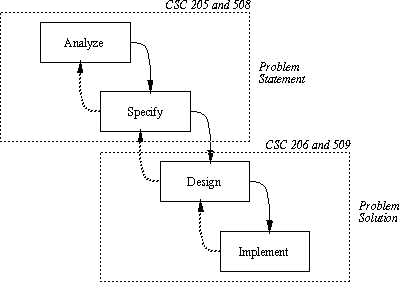
Figure 1: Software system lifecyle.
- Requirements Analysis determines what end users want and need from a software system.
- Specification formally defines user requirements.
- Design defines and organizes the major operational components of the system.
- Implementation defines operational details in a programming language.
- The result of requirements analysis and specification is a document that specifies what the system does as opposed to how it works.
- In general, requirements analysis and specification are the domain of CSC 205/508.
-
The 508 requirements and specifications from last quarter are located at
following URL:
http://kdat.calpoly.edu/~gfisher/projects/work/inferno
-
Objective -- to construct an Integrated, Graphical, Uniform-Language, Multi-
Platform Software Development Environment for use by undergraduate software
engineering students.
- Integrated means that the environment will provide integrated support tools for all of the major phases of software development, most particularly for requirements, specification, design, implementation, and testing.
- Graphical means that the environment will provide a variety of graphical viewing and editing tools to aid in the software development process.
- Uniform-Language means that tools in the environment that use a textual language will use the same common language; in addition, the environment will provide features for the addition of new common languages in an efficient manner.
- Multi-Platform means that the environment will support the development of software on and for a number of common platforms, most particularly UNIX, PC, and Macintosh.
-
Figures 2 and 3 show the initial UI screen and expanded command menus for the
environment.

Figure 2: Initial user screen.

Figure 3: Expanded command menus.
-
Major components of the environment are:
-
Top-Level tools that provide a process-oriented GUI project; the
specific top-level tools are the following:
- process navigator, for viewing the software process and launching development tools
- artifact navigator, for viewing the software artifacts produced by the steps of the process
- historical navigator, for viewing the version history of artifacts
- command-line navigator, providing a textual form of process navigation useful in particular for scripting
-
Development tools tools for the five ordered steps of the process:
- requirements analysis
- specification
- prototyping
- design
- implementation
-
Development tools tools for the four pervasive steps of the process:
- configuration management
- testing
- project administration
- project documentation
- General text and graphics editing tools, with customized functionality based on their context of use.
-
Top-Level tools that provide a process-oriented GUI project; the
specific top-level tools are the following:
-
Adhere to the specification
- Any deviation from the specification must be recorded and approved in a Specification Change Order (SCO).
- The specification plus SCOs form a binding contract between the customer and the design team.
- No changes to specification can be made without consulting with the customer and completing a signed SCO.
-
Achieve design quality goals:
- Traceability -- elements of the design trace back to corresponding elements of the specification.
- Modularity -- elements of the design are organized into logically cohesive modules.
- Portability -- the design is sufficiently general that it can be implemented on a variety of platforms and a variety of (related) programming languages.
- Maintainability -- the system is designed such that it can be easily repaired and enhanced.
- Reusability -- where appropriate, modules are designed to promote their reuse in other (future) designs.

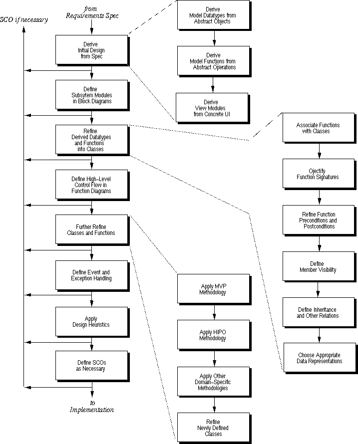
Figure 4: The 206/509 design process.
- Derive Initial Design from Spec. Based on the requirements specification, including the formal RSL specification, derive the initial rough design.
- Define Subsystem Modules in Block Diagrams. Determine the major subsystems, which are roughly identified as the separate user-level processes in the specification; draw the high-level relationships between these modules in a block diagram.
-
Define Initial Object Modules using Class Diagrams. Begin the
object-oriented design process by:
- associating each function with an appropriate class,
- "objectifying" function signatures,
- refining preconditions and postconditions for each function,
- defining class member visibility,
- defining inheritance and other relations,
- choosing appropriate data representations.
- Define High-Level Control Flow in Function Diagrams. Begin to determine functional control flow, i.e, what functions call what other functions.
-
Further Refine Classes and functions. Continue the design
refinement by applying well-known design methodologies:
- MVP -- model/view/process, which organizes the design to achieve maximal separation between graphical user interface modules and underlying data processing modules.
- HIPO -- hierarchical input/process/output, which organizes the design of the non-graphical components of the interface and processing
- Other domain-specific design methodologies, such as client/server, transaction processing, etc; such mythologies often embody what are called design patterns or design architectures
-
These methodologies prescribe how to refine newly defined classes, which
entails some or all of the following steps
- refining class data representations
- adding new member functions as necessary
- defining new superclasses and subclasses
- adding class/subclass details to the class hierarchy diagram
- defining preconditions and postconditions for all new functions
- Define Exception Handling. Based on methodology guidelines as appropriate, define system events and exceptional conditions. For events, define the functions that respond to them. For exceptions, define where they are recognized and where they are handled.
- Apply General Design Heuristics. These include heuristics to minimize inter-module coupling and maximize intra-module cohesion.
- Define SCOs. Define Specification Change Orders and update the requirements and/or specification artifacts as necessary.
-
The employs techniques from a number of design methodologies, including:
- The OMT (object modeling technique) of Rumbaugh, et al.
- The structured design technique of Yourdon, et al.
- the MVP (model, view, process) technique used originally with the Smalltalk language.
- the HIPO (hierarchical input, process, output), developed originally at IBM.
- The process works well for information processing systems with substantial end- user interfaces, which are the types of systems developed in 206 and 509.
- For other types of system, similar process steps can be used, but possibly in a different order, and with different domain-specific methodologies.
-
Other major system types include:
- Realtime systems, such as communications software.
- Utility systems, such as compilers and operating systems.
- Embedded systems, such as device drivers and process controllers.
- One of the problems to be confronted in designing from a formal specification is the translation from the requirements/specification language into the design/implementation language.
-
It is likely that specification languages differ from programming languages,
since there are different forces influencing the design of the two types of
languages.
-
Specification languages:
- The spec language should be more abstract than a programming language, and free of any implementation-level features.
- It should be understandable to non-programmers at some level.
-
Programming languages:
- Provide enough power to build efficient implementations.
- Provide enough features to organize implementations modularly.
- Understandability for non-programmers is not an issue.
-
Specification languages:
- The two languages we're concerned with are RSL and Java, so we'll use their terminology.
Now on to details of each step of the design process
-
An RSL-to-Java comparison table is shown Table 1
RSL Java module package object class or simple type operation function function function pre/post conds comments only and composition class data members or composition inheritance (enumeration) list composition varying implementations recursive composition recursive class definition Table 1: RSL-to-Java comparison.
-
Each RSL composite object in the specification is transformed into a Java
class, with exactly the same name.
- Each and'd component in an RSL object is transformed into a protected data member of the transformed class.
- Each or'd component in an RSL object is transformed into a protected data member in a subclass.
- Each list or recursively defined component in an RSL object is transformed into an abstract type data member in the transformed class, to be refined later into an appropriate concrete data representation.
-
Each RSL atomic object is transformed into a simple Java type.
- RSL type integer is transformed to Java int.
- RSL types real and number are transformed to Java double.
- RSL type string is transformed to Java String.
- RSL type boolean is transformed to Java boolean.
-
Each RSL operation is transformed into a Java function definition, with an
equivalent input signature, and equivalent output signature if possible.
-
An RSL input of the form
is transformed to a Java formal function parameter of the form:name:type
type name
- An RSL operation with a single output is transformed to a Java function that returns that output type.
- An RSL operation with more than one output is transformed to a Java function that returns void, with a comment indicating the multiple return types. This function will be refined later in the design process.
-
An RSL input of the form
-
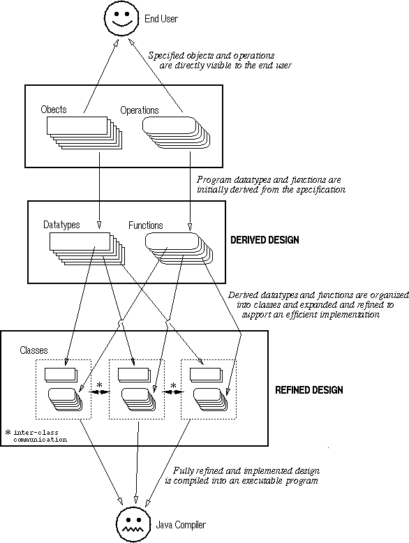
Figure 5 is a stylized illustration of how the derivation and subsequent
refinement steps of the design process relate to one another.

Figure 5: Stylized view design derivation and refinement.