Requirements for Page Setup in Jdraw

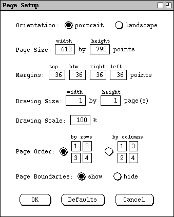
Figure 1: Pages dialog.
The `Page Size' values define the size of a page in printer's points. Per normal typography standards, a point equals 1/72 inch. The `Margins' settings define the outer edges of the page on which printing does not occur. When a drawing is printed, the portions of the drawing within each page boundary are printed on a page of the specified size within the specified margins. When possible, Jdraw determines page size and margin settings from the currently selected printer and displays those as the default values in the page setup dialog. When Jdraw cannot determine page size and margins from the printer, it uses the defaults shown in Figure 1. The size of 612 by 792 points equals the standard page size of 8 1/2 by 11 inches. The 36 point default margins equal 1/2 inch each.
The user can adjust the page size and margin settings to accommodate the paper size and margin requirements of different printers. In so doing, the user must be careful not to enter page size or margin values that cannot be accommodated on a particular printer. For example, if the user enters values of 0 for all margins, and the printer cannot print on 100% of an 8 1/2 by 11 sheet of paper, then portions of the drawing that extend into the unprintable margins will be lost on the printed page.
The `Drawing Size' settings define the number of printable pages in a drawing. The default is 1 page. The user can draw on a canvas beyond the printed page boundaries, but none of the drawing outside of the page boundaries appears on a printed page.
The `Drawing Scale' value defines the scale of the drawing relative to the page. This value is independent of the drawing zoom level. The default scale is 100%.
The `Page Order' selection defines the linear order in which pages are sent to the printer. The default selection is by rows, meaning that pages are sent to the printer in row-by-row order. The other selection is column-by- column order.
The `Page Boundaries' selection defines whether boundaries are visible on the drawing canvas. When shown, the boundaries are drawn as light-grey dashed lines. The default is `show'. When `hide' is selected, the page boundaries are still present in the drawing, just not visible on the canvas.
After changing any page settings, the user can press the `Defaults' button to restore the system-defined default values.
Figure 2 shows the default page configuration for a simple drawing with three
rectangles.
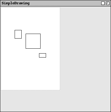
Figure 2: Default page layout for a simple drawing.
Figure 3 shows the user having changed the page settings for orientation, page
size, margins, and drawing size.
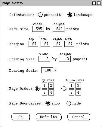
Figure 3: Page dialog edited.
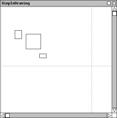
Figure 4: A 2x3 page layout with scrollbars.
With the larger number of pages, the entire paged area is not visible in the drawing canvas. When this occurs, the system adds vertical and horizontal scroll bars to allow the user to scroll throughout the entire paged area of the drawing. Scroll bars are added in this way whenever the size of the canvas window is smaller than the size of the paged drawing area at the current zoom level. If one dimension is fully visible in the window, only a single scrollbar is added for the not-fully-visible dimension.
The unpaged grey area of a drawing is always drawn down and to the right of the
paged area. In this way, the upper left corner of the drawing canvas always
coincides with the upper left corner of the first page, whenever the paged area
is fully visible in the canvas window. When the paged area is scrolled, the
rightward and downward scrolling extends to the right and bottom edges of the
paged area, and not beyond. For example, Figure 5 shows the result of the user
having scrolled Figure 4 all the way down and to the right.
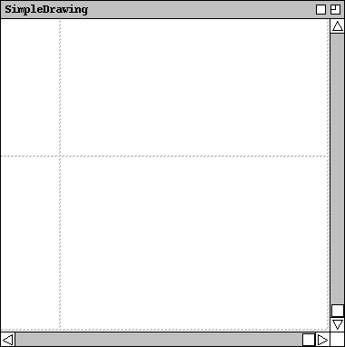
Figure 5: The 2x3 page layout scrolled all the way down and right.
Given the preceding scrolling rules, the only time the unpaged grey area is
visible in a canvas window is when the window is larger than the paged area.
This occurs when the default drawing size is smaller than the default window
size, as in Figure 2. It can also occur when the user enlarges a window or
zooms out in a window. For example, Figure 6 shows the result of the user
zooming to 0.5 magnification from Figure 4.
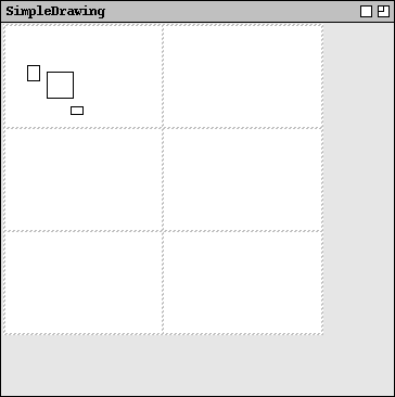
Figure 6: The 2x3 page layout zoomed out.
Figure 7 illustrates the user having restored the drawing zoom to normal, and
set the `Drawing Scale' value to 200%.
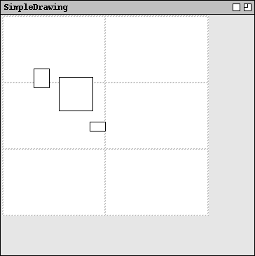
Figure 7: Page layout with normal zoom and drawing scale set to 200%.
Figure 8 shows the result of changing the `Page Boundaries' selection
to `hide'.
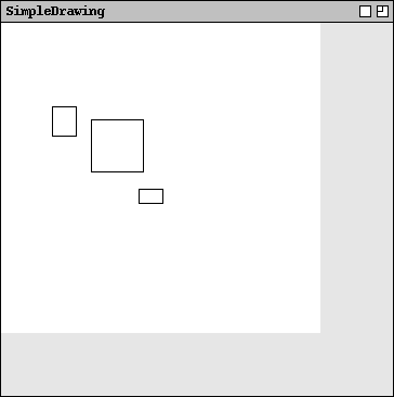
Figure 8: Drawing with page boundaries hidden.
The page size and margin values define the absolute size of a drawing, independent of screen resolution, printer resolution, or paper size. At normal zoom and 100% page scaling, the actual size of drawn objects on both the screen and printed page is determined by the page size and margin values. In order for object sizes to be accurately rendered on the screen, the screen size of a page equals the full page size minus the margins. For example, with the default page size of 612 by 792 points, and default margins of 36 points, the size of a page on the screen is 540 by 720 points. In this way, objects drawn on the screen, and in particular objects drawn across page boundaries, are both displayed and printed properly to scale.