Project Description
For my final project for Intro to Computer Graphics, I created first-person jet-powered stooter.
When thinking of possible paths I could take a final project in this class, I decided I wanted to persue something that contained some sort of realistic simulation of reality. Inspired by Zoe's talk of heightmaps, I determined that I would employ heightmaps to perform some sort of terrain generation. I also wished to include a target shooting aspect into this game. My final plan that I was to proceed with was a game where the player flys a jet in an environment modeled after the real word, and can shoot and destroy targets. For this to become a reality, I needed to accomplish the following points:
- Locating downloadable heightmap data from the earth
- Stitch together heightmap files into a composite heightmap for a large environment
- Write a heightmap parser to take in a heightmap and convert it into a ground mesh
- Write a texture coordinate generator to apply a texture to the ground mesh
- Properly rotate the camera basis vectors to enable 3 axis rotation
- Simulate the flying properties of an aircraft
- Keep track of and calculate paths of projectiles
- Placement of targets and collision detection with projectiles
- Apply particle system explosions for hitting a target
- Integrate use of a gamepad
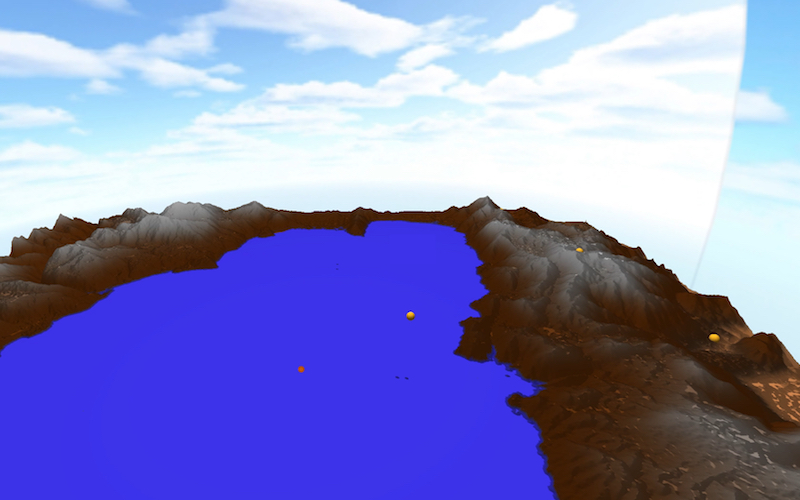 view of the environment, with yellow target spheres
Generating the terrain
Almost all modern video games these days drop you into a world with a realistic environment. Instead of using a flat plane for the playing surface, games include rolling hills, cliffs, mountains, and other terrain features you would see in the real world. To convey such data in the computer world, game producers use what is called a heightmap. A heightmap is simply 2D bitmap image where the color of each pixel (usually greyscale) corresponds to the elevation of the floor at that point. For a greyscale image, black represents zero elevation, white represents 100% elevation, and grey represents any point in between. Heightmaps can be generated from a variety of sources. The easiest method of heightmap generation is using an image editor, such as Photoshop, and generating fractal noise. This will generate an image that resembles a cloudy sky, resulting in fairly realistic terrain, which is the method I used initially for testing.
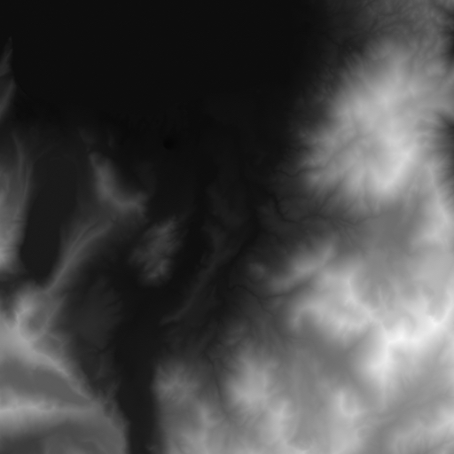 Example of a heightmap
Another option is to use programs that are designed specifically for generating ultrarealistic heightmaps, such as Terragen. However, I didn't have the time to learn how to use this somewhat complex program. I decided I wanted to use real terrain from the earth. As it turns out, the US Geological Survey has an enormous public database of elevation data, among many, many other databases. The USGS' website, for unknown reasons, served me completely black images of any terrain I requested. Thankfully, I found another site, Terrain Party, that both served me usable heightmaps, and was much easier to use. (The data they use comes from the USGS as well). I wanted to recreate the place I grew up, and my favorite place in the world: Lake Tahoe.
Although Terrain Party is easy to use, there isn't a way to enlarge the bounding box for the terrain download. To download the entire Lake, I had to download four separate tiles, and stitch them together in Photoshop. Because each tile has its own high and low elevations, the white and black points for each image represent different absolute elevations in the real world. For each tile, I adjusted the levels of the whites and blacks to become uniform with the tiles around it, using the Lake's surface elevation as a reference for all tiles. There were still some visible boundary lines, so I used the spot healing tool to remove them. The result is a large, composite heightmap of Lake Tahoe.
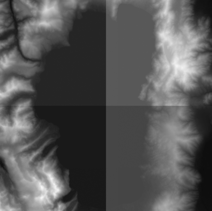 Uncorrected Tiles
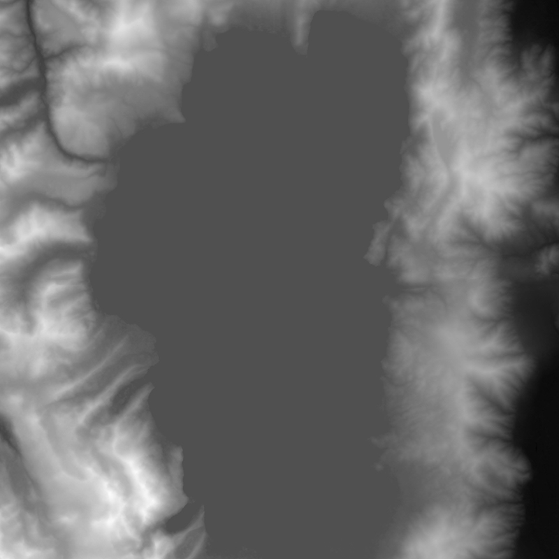 Corrected Composite Heightmap of Lake Tahoe
After creating the desired heightmap, I had to convert the bitmap image into a mesh for OpenGL to use. In other words, the image needs to be used to create a 2D array of triangles, where the vertices of the triangles corresponds to the "intensity" of the color at that point. This was accomplished creating two triangles for each set of four points, as shown in the diagram below:
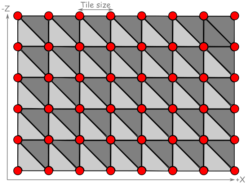 Triangle generation. Credit: blogs.igalia.com
The easiest and most efficient way of accomplishing this is to loop through the 2D array of pixels and, for each pixel "quad", fill a Vertex Buffer Object (VBO) containing the vertices of the two triangles, making careful note of the order in which the vertices are added, which is important for calculating normal vectors for each triangle. While filling the VBO, an Index Buffer Object (IBO) is created which references which points are to be used for each triangle. Because a single point can be referenced multiple times, using an IBO instead of redefining the same point for multiple triangles is very efficient. From there, the normals are calculated using borrowed code from previous labs, which we wrote ourselves.
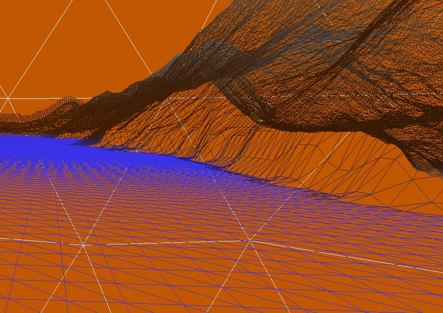 Wireframe of the terrain, showing the individual triangles that were generated
Applying Textures
After the the terrain generation was working properly, the next step was to apply texturing to the mesh to make it look more realistic. I created a semi-realistic looking texture by taking the heightmap and coloring it myself, coloring the surface of the lake a solid blue, and using the actual height data as a gradient for the other terrain. This resulted in snowy looking mountains and a dry, desert-looking floor for the Carson Valley.
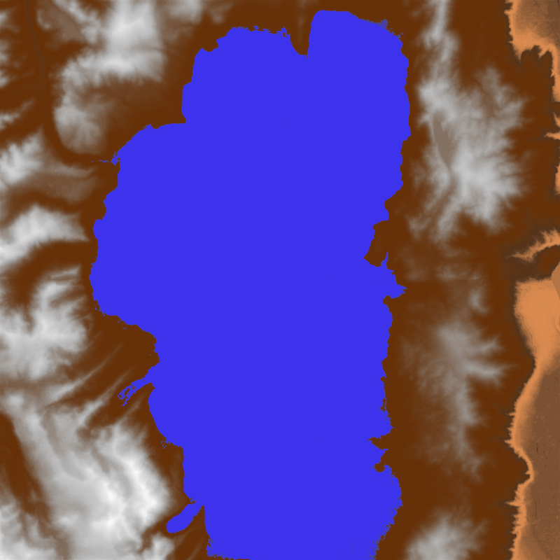 Texture I created for the terrain.
For each vertex in the terrain object, a texture coordinate needs to be specified. Since the object we wish to texture is essentially a flat plane, calculating the texture coordinated is pretty straightforward. Because every pixel in the heightmap file corresponds to a vertex in the mesh, we can associate each pixel color with the appropriate vertex. Texturing, along with utilizing Phong reflectance calculations, is how the final terrain is colored.
Simulating Aircraft Movement
In our previous labs and projects, our camera was limited to panning and tilting, but was unable to roll or tilt up or down past 90 degrees. This is because the "up" vector for our camera was fixed, causing problems when the "look" vector becomes parallel with the up vector. Aircraft, as we know, are free to rotate in all 3 axes, and can flip upside down. To deal with this, I needed to continually rotate the three basis vectors of the camera so that they are always perpendicular to eachother. GLFW contains an experimental vector library that allows, among other operations, the ability to rotate a vector around another vector. When, for example, the camera/plane tilts up, it uses the "strafe" vector of the camera to rotate both the look vector and the up vector of the camera by the appropriate angle. If the plane rolls, it uses the look vector to rotate both the strafe vector and the up vector, causing the camera to roll. Finally, if the plane moves in the yaw axis, the up vector is used to rotate the strafe vector and the look vector. The result is the ability to rotate in any axis or combination of axes.
To simulate the actual movement of the aircraft, linear and angular camera velocities are kept track of. When a control event is triggered, the magnitude of the event is accumulated in the appropriate variable. When an inverse event is received, it takes time to "drain" the variable to 0 and back in the negative direction. This simulates the inertia an object would have when attempting to speed it up, slow it down, or reverse a rotation.
Targets and Projectiles
Keeping track of the targets, projectiles, and explosions was the most involved part of the project. To produce a projectile, I alternated the position of it to either the left or right of the view. To animate the position, I took the look vector and added it, multiplied by the time its been "alive" for, to the original position. Once its life is up, it's deleted from the list. The targets were placed manually on the map. Originally, I wanted the targets to be randomly placed on the map with heights taken from the heightmap, but I was unfortunately unable to get that to cooperate. To determine when a projectile hit a target, a simple sphere-sphere intersection calculation was used. Essentially, if the distance between the target and the projectile is less than the sum of their radii, a collision has occurred. When this happens, a particle system is initialized at the target's location, with its parameters tweaked to resemble an explosion.
Integrating the Gamepad
Out of all of the hurdles I had to jump over for this project, the gamepad integration was by far the easiest. GLFW provides an easy to use API to interface with the gamepad, returning the number of buttons and joysticks on the device. Every time a frame is rendered, it polls the gamepad and returns the states of all of the buttons and joysticks. From there, it is very easy to manipulate flight control variables.
Future Work
If I were to add more features to this project, I would first add text display support, because text feedback is incredibly valuable for a game to have, such as displaying the current score. I would also add collision detection for the terrain. If I were to be really courageous, I would attempt to add some sort of dogfighting gameplay using our knowledge from the Computer Networks course.
Resources
- Easy to use site to download real heightmaps http://terrain.party
- USGS global database https://earthexplorer.usgs.gov
- Heightmap conversion tutorial http://www.mbsoftworks.sk/index.php?page=tutorials&series=1&tutorial=24
- Another heightmap conversion tutorial https://blogs.igalia.com/itoral/2016/10/13/opengl-terrain-renderer-rendering-the-terrain-mesh/
- This CSS template, borrowed from Tyler Dahl from a previous 471 web page! http://users.csc.calpoly.edu/~zwood/teaching/csc471/finalW16_3/tcdahl/index.html