Ray Tracing with Meshes and Space Partitioning!
Thomas Soria
CSC 471 Spring 2013
Zoe Wood
This project is working off Marc Zych's Ray Tracer which can be accessed on GitHub.
Just like Marc's, this code is open-source! Fork it on GitHub.
Triangle Ray Intersection
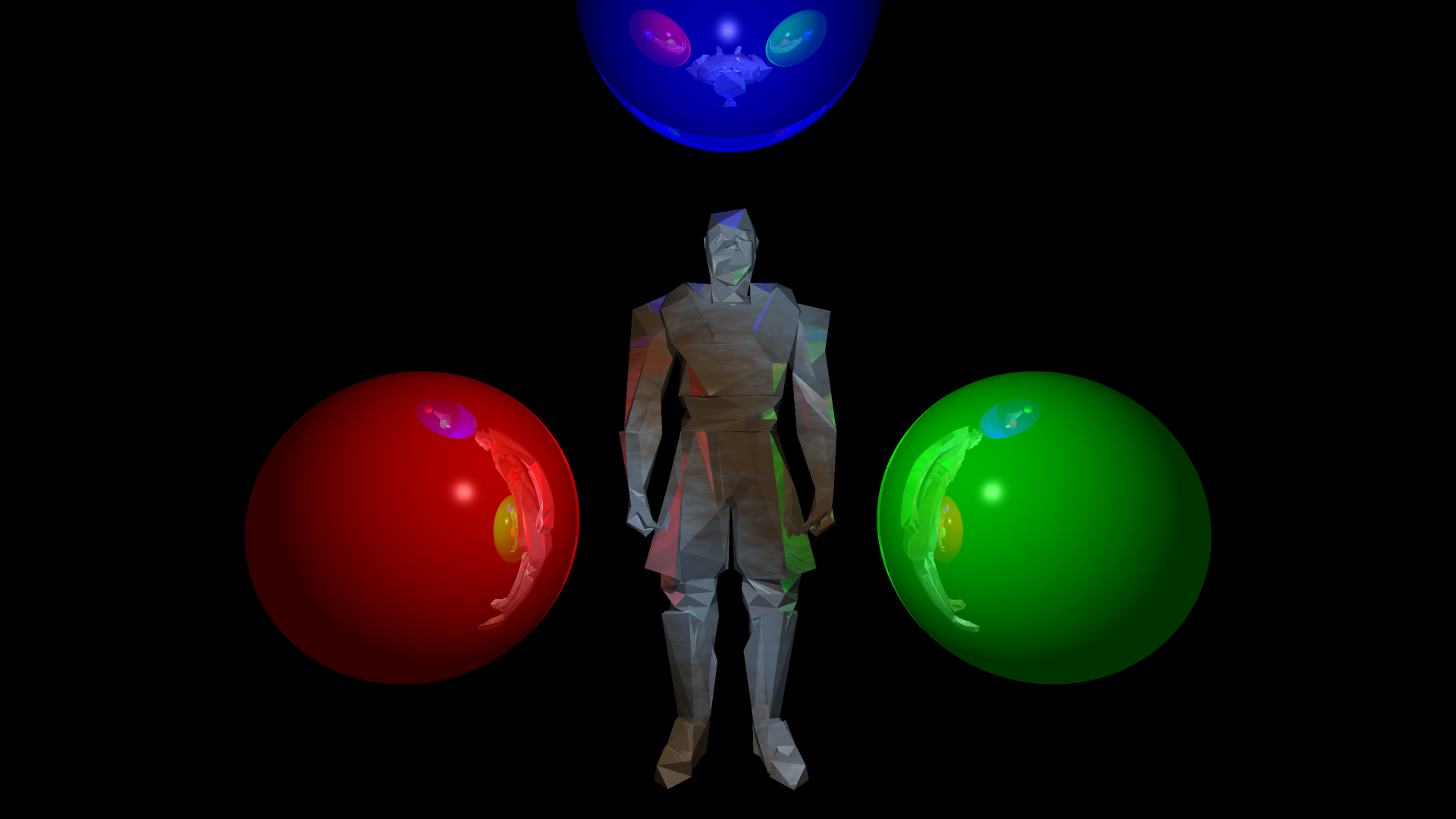
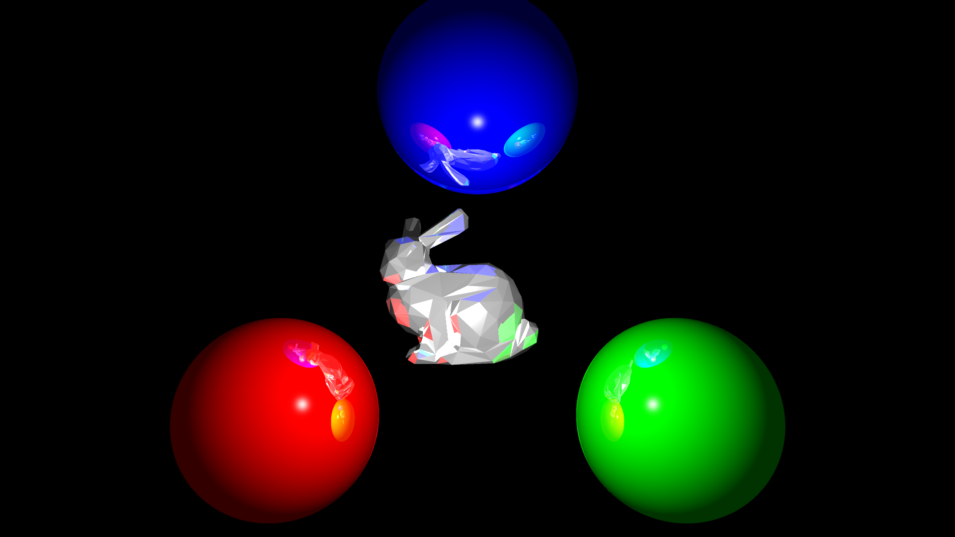
To incorporate meshes into the ray tracer, logic for ray triangle intersection had to be written. This implementation treats each triangle as its own object much like the sphere's implementation done previously.
For the actual implementation, please reference:
Mesh Parser
I wanted scenes to read meshes rather than only feeding it the triangles which represent the model. There isn't much error checking done at this stage, so it assumes the given mesh is formatted correctly (Vertices followed by Faces.) the logic is contained in the function readModel() and can be found here. Each face becomes its own triangle object so there is no one model object.
Mesh Usability
The problem with meshes is that you don't really have a guarantee on how big or where it is. 4 parameters were added to the syntax for models in scenes which represent the (X, Y, Z) location of the mesh (the mesh is centered at that point) and the max size of the object. (Imagine it like a diameter for a sphere, and the mesh is stretched (with its aspect locked) to fill up the sphere.
Space Partitioning!
It was initially going to be binary space partitioning, but after much thought, it became apparent that this was a bad idea.
The Problem:
In order to balance trees, geometry is usually cut. Doing this to spheres is a HUGE nono. I'm sure it's somewhat possible, but it's a lot more trouble than it's worth and creates way too much new geometry.
My Approach:
I decided to go with a binary space tree of sorts. Every 'parent' has two children
which represent its 'left' half and 'right' half. I put these words in quotes
because each time I split the group in half, the axis is changed round robin
style from X->Y->Z->... to make several cubes of objects. The same object can
be in multiple halves if it happens to be in both (such as as a large sphere.)
I then had to implement a bounding box class and learned a lot about various
methods to test intersections with rays. AABB Ray intersection was what I eventually
settled with after tackling several algorithms.
When you run the program, you'll see the skeleton of the tree printed out.
It works great with models with many triangles, but become quickly useless when
massive spheres come into play. You'll notice that running modelTest1 gives you a smaller
tree with each leaf still containing several objects because of the spheres, while modelTest3
gives a MUCH more divided tree.
For the actual implementation, please reference:
Bounding Logic:
Results
Relatively disappointing? First off, when splitting the tree in 'half' for every iteration, any objects that occur on both halves
are placed in both children. This means that huge objects (such as spheres with huge radii) removes most of the benefits of this tree.
The best results can be seen on scenes consisting of many, smaller triangles (put simply: many meshes.)
The total time saved changes depending on the machine running the ray tracer, but on average: scenes with spheres get a 5% speedup while mesh-only
scenes got around 10%. I found this surprisingly low considering that for every ray, the amount of objects checked is usually decreased
by several hundred (depends on the scene of course)
Test it yourself and add to it!
To build, simply run make! (From /src/ of course)
Usage: ./RayTracer sceneFile superSamples depthComplexity [outFile]
An example command I usually used:
- make && time ./RayTracer ../scenes/modelTest1.scn 1 1 && open out.tga