Introduction
For my final project in CPE 471 during Winter quarter 2015, I implemented a deferred renderer.
The program renders a scene using a pipeline with the following techniques:
- Deferred Phong shading with different materials and both point and directional lights
- Ambient Occlusion
- Skyboxes
- Bloom
- Depth-of-field
- Fire Simulation
Each of these technologies is discussed and sourced on this page. Links to the various technologies are available on the sidebar.
Referenced sources and further reading are given per-topic. Screenshots are provided to both explain and showcase the implemented technologies.
The final product of the program was a nighttime forest scene with mountains in the distance and a lit shrine dedicated to the Stanford Bunny
as pictured below:
Full Pipeline Diagram
 Click to enlarge
The full pipeline starts by running objects through the geometry shader and storing the output in the G-Buffer. These buffers are used as the
input to the ambient occlusion pass, which is blurred to remove artifacts. This blurred occlusion map and the G-Buffer data combined become the
input to the Phong lighting pass, which draws the lights using stencils and light volumes. The skybox is drawn on top of this lit output to
fill in the visible background areas. Separately, the flames get sent to the flame shader, the output of which is blurred.
The final image is a combination of these two separate drawing stages. This image is sent to post-processing, where a copy of it is blurred
using the depth of field method. If bloom is disabled, this blurred output is the only thing drawn to the screen. If bloom is enabled, the
pre-blurred image is output to the screen and the blurred, luminance-filtered image is added to it to receive the final image.
Deferred Shading
Weaknesses of Forward Rendering
To know what deferred rendering is, we must first discuss what it is not. A typical pipeline in computer graphics, like those discussed in this
class, uses a technique termed "Forward rendering." In this paradigm, each object is individually sent through the full pipeline at once.
Usually, a vertex shader positions the object in the world, after which it is rasterized and a fragment shader is run per-fragment, usually
computing the color at that point and outputting it to the buffer. Using depth testing, we can prevent performing the full lighting calculation
on every possible fragment by ignoring occluded fragments.
However, what happens when closer objects are rendered on top of the already-drawn scene? Then the new object will replace all of the
now-occluded pixels, meaning all the time spent computing lighting in that part of the scene is wasted. Furthermore, how do you apply multiple
dynamic lights to the scene when forward rendering? Usually this involves costly loops across every light in the scene for every fragment,
significantly increasing the complexity of the lighting calculations. This can lead to very slow shading whenever more than a few lights are computed.
Basics of Deferred Rendering
These are the weaknesses deferred rendering seeks to alleviate. The technique works by running all geometry through a very similar vertex shader,
but instead of immediately calculating lighting on each object in the fragment shader, it simply draws the interpolated data into textures attached
to a framebuffer (called the geometry buffer or "G-Buffer"). What does this give us? Well, because we've used depth testing to only draw the closest
fragments into the textures, once all the geometry has finished rendering, the G-Buffer will contain information on only the fragments nearest the
camera a.k.a. the visible pixels. This means that we've kept all the data we need in order to light every visible pixel, while discarding all the
data needed for occluded pixels, and we did it without wasting time on costly lighting calculations! Our G-Buffer now looks something like this:
 Viewspace Position
 Viewspace Normal
 Diffuse Color
 Depth
Depth
Now, in our second pass of the deferred shader, we sample the G-Buffer and use this data to complete our lighting calculations. The actual execution
of the Phong shader is relatively unchanged - the main difference is that our material properties, point positions, and point normals are now coming
in view textures instead of varying or uniform values.
Stenciling and Light Volumes
Furthermore, we can limit our lighting calculations not only to visible pixels, but also to only those visible pixels that will actually be affected
by the lights. For a point light, we accomplish this by lighting only those points within a radius of the light representing the distance light can
travel from that point source based on its attenuation. For instance, a weak light might only be capable of affecting points within a few units of
it - for points beyond that radius, even if we ran the lighting calculation on those points, the contribution would be rounded to 0 due to the
limited precision of the variables storing these RGBA values. (In a typical 8-bit buffer, only 256 unique values can be expressed for each component,
meaning values under 1/256 or about 0.004f will be rounded down to 0, or no contribution to the scene.) We calculate the maximum radius of the point
light, then render a simple sphere at the light's position with this radius. When the sphere passes through the vertex shader and into the fragment
shader, the sphere's fragments exactly correspond with the fragments within the lighting's radius. We can run the lighting calculations for this
light on just these fragments, giving us a simple method of ignoring all points which will be unaffected by the light and would have wasted previous
GPU cycles. Lastly, because the projection of the sphere might include pixels significantly in front of or behind the sphere, we use a stencil pass
of this "light volume" to remove these pixels before running any wasted lighting calculations on them.
This technique of stenciling and shading within a light volume can be applied beyond point lights. For spotlights, a similar method can be used with
cones instead of spheres. For directional lights, which will affect every pixel in the scene, we don't need to stencil - we just render a fullscreen
quad to ensure the lighting calculations are applied on every pixel in the scene.
Note that lighting is done additively. First, the output is cleared to black. Then, we loop through each light and perform the stenciled lighting
calculation on its light volume, adding its contribution to each pixel using glBlendFunc(GL_ONE, GL_ONE). Our final result will be a sum per-pixel
of the contributions of every light.
Final Thoughts
To recap: deferred shading solves several efficiency problems encountered in forward rendering, where expensive lighting calculations are often
performed needlessly. This makes adds lights to a deferred shader very easy and cheap. My own scene has around 40 dynamic point light sources, but
numbers in the hundreds are definitely feasible. This isn't to say that deferred shading is altogether superior, though. Because it involves many
texture reads and writes, the video card's memory space and bandwidth become much more important of factors. In addition, because only the closest
items are stored in the G-Buffer, a transparent object will overwrite anything behind it, making transparent objects tricky in a truely deferred
shader. For this reason, many programs use a mixture of deferred shading for opaque objects and forward rendering for transparent objects, as each
has its strengths.
Sources and Further Reading
Screen Space Ambient Occlusion
Motivation for Ambient Occlusion
The Phong shading model separates three interactions between light, objects, and our eye. The diffuse component represents the amount of direct
light scattered by a surface and is applied to the light-facing surface of the object. The specular component represents the amount of direct
light scattered in the direction of the viewr and is also applied to the light-facing surface. The final component, ambient light, represents the
amount of light which bounces off different objects in the scene and makes its way to all parts of the scene, both light-facing and non-light-facing.
This is a nice way to represent the brightness of the scene as a whole, but it fails to capture an important trait of real light. Look at the corner
of your room and notice that it is slightly darker than the surrounding surfaces. This is because the ambient light applied to that corner is limited
in both the angles it can approach and leave the corner without hitting the adjacent walls. In general, creases and cracks are darker because of this
phenomenon, and ridges are conversely brighter. This effect is represented by ambient occlusion - the method of modeling the amount of ambient light
that reaches any given point.
 Shrine pedestal, no SSAO
 Shrine pedestal, SSAO
Conceptual Implementation
In order to calculate the occlusion factor for each point, we cast rays from the point out into the scene. Because points inside the object are
uninteresting to us, we only cast our rays in the general direction of the point's normal (specifically, in a hemisphere oriented on the surface on
the normal's side). If the ray intersects another point, it adds to the occlusion factor of the pixel based on the distance before the ray's
intersection. Thus, tight cracks with very few unoccluded rays and very short occluded rays have a very high occlusion factor. This multiplier is then
applied on the ambient component of the lighting calculation, such that more heavily occluded points receive less light. Note that the multiplier is
only on ambient lighting - this way, a crease receiving direct light will still be relatively bright (though less so than the surrounding areas), while
a crease facing away from the light will receive almost no light and be nearly black.
Screen Space Implementation
In order to compute the occlusion factor of a point, we need the positions of this point and all its surroundings, as well as the shape's normal at that
point. This meshes nicely with a deferred shader, as all of this information is already available in the G-Buffer from the geometry pass. The general
approach per fragment starts by reading the point's position and normal from the buffers. Then, several surrounding points in the buffer are chosen
based on the current fragment's coordinates and the positions of these points are retrieved. We compute the vector between the sample point and the
current point. To ensure that the sampled point is within the desired surface-aligned hemisphere, we check the dot product between this vector and the
current point's normal. If this dot product is negative, the vectors are oriented in opposite directions and the sample is not within the hemisphere.
Else, the sample is within the hemisphere and we add to the occlusion of the current point based on the length of the computed vector (the distance
between the points) such that a nearby sample occludes the current point more than a far away sample might. Typically this is implemented with many
samples (16 in my project) in order to improve the quality of the output, though of course more samples are more costly. In addition, the output is
often blurred, as SSAO can cause some patterns in the output according to the way random rays are chosen, and a simple blur helps hide this issue.
 SSAO shader map, no blur
 SSAO shader map, blurred
 Bunny shrine, no SSAO
 Bunny shrine, SSAO, no blur
 Bunny shrine, SSAO, blurred
Final Thoughts
Like other parts of deferred rendering, this approach benefits from having the necessary inputs already stored such that only the visible geometry
has its ambient occlusion computed, saving valuable GPU time for only the pixels that will make it to the screen. However, again deferred rendering
suffers from losing information about the scene by attempting to compress information about the whole world down into a 2D texture. This time, the fact
that hidden geometry isn't stored and available for the ambient occlusion calculation leads to a weakness in the accuracy of the model. For instance, a
ray might have intersected an object behind something else in the final scene, but this object isn't stored in the G-Buffer, so that ray now appears to
be free of intersections. Despite this weakness, the SSAO calculation gives very satisfying results, faking a shadow effect that helps provide definition
to the creases in scene geometry (it makes things "pop" by helping simulate depth) and doing so with an acceptably low performance hit.
Sources and Further Reading
Skybox
Motivation for Skyboxes
A skybox is basically as the name suggests - it is a box on which the sky is drawn. It is used to simulate objects in the distance to which the viewer
never really gets closer. For my project, the skybox included a few mountains in the distance and a bit of a cloudy, overcast scene overhead. Because
for the purposes of our scene the viewer's perspective of the sky and distant mountains doesn't ever have to change, why bother rendering them in full
and wasting precious GPU time?
Implementation of Skyboxes
Instead, we draw the distant background as a set of seamless textures providing a full panoramic perspective without any visible seams. We then combine
these textures into a GL_TEXTURE_CUBE_MAP and attach this map to a piece of geometry (often a cube/"box", hence the name, but sometimes a sphere, as in
my implementation). The skybox is centered on the camera before rendering in order to give the illusion that the background never moves, even though it
is actually just moving along with the virtual camera. The shader samples the cube map based on the position of the final rasterized fragment - note that
a cube map texture is sampled via a three-dimensional vector, allowing all six faces to be sampled based on their orientation relative to the center
point. This behavior fits perfectly, as our skybox must be sampled in any direction based on orientation relative to the center point, the camera. The
end result is a background which appears to stay fixed in space relative to the viewer no matter how the camera is panned or repositioned.

Taking Advantage of Depth Testing
The skybox is usually rendered near the end of the pipeline with depth-testing enabled. This ensures that any parts of the viewport with foreground
geometry remain visible, while only the missing areas are filled in with the background. This performs better than rendering the skybox prior to scene
geometry, as items in the scene are just going to be drawn over the skybox anyway. This fits with our general goal of only spending time rendering
visible fragments, allowing us to quickly ignore occluded fragments.
Sources and Further Reading
Bloom
Motivation for Bloom
Bloom is a postprocessing effect used to simulate the way our virtual camera would interact with very bright lights and brightly lit objects. It makes
lights look stylistically harsh by giving them the appearance of being even brighter than they actually are. This is simulated by having the light
"bleed" into surrounding portions of the scene to simulate a trick of the eye. Think about looking at a window receiving direct afternoon sunlight and
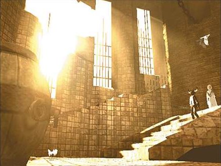
recall the "fuzziness" of the window's shape as it seems to radiate light nearby too bright to comfortably look at. This is the effect bloom is simulating.
An example of bloom from one of the earliest games to use it, Ico:
Implementation of Bloom
Typically the "fuzziness" of Bloom is achieved via a simple Gaussian Blur on the final image before actually drawing to the screen. This blurred copy
is then reapplied additively to the unblurred version of the image. This brightens all parts of the scene and bleeds geometry into surrounding areas. The
effect is fine for something like Geometry Wars, where every object is intend to have a sort of flourescent glow, but in typical situations - especially
darker scenes like the night scene in my project - the effect is out of place and disorienting.
Modifying Bloom Based on Perceived Luminance
Although the aforementioned method already brightens very bright portions of the scene, as desired, it had far too significant an effect on the dark
portions of my scene for my preference. The scene as a whole had a fake look, likely due to the slightly apparent blur and the very marginal brightening
of dark areas. Never underestimate the ability for a relatively simple modification to just look "wrong" - humans are very visual and very attuned to
small visual artifacts that don't match their expectations.
This motivated a quest to tweak the bloom effect to be even less obtrusive on the dark portions of the scene while maintaining the effect on the
brightest areas. An early attempt discarded fragments below a specific threshold color, such that parts of the blurred scene were entirely dropped if
they were darker than the threshold. This allowed areas of the scene in darkness (and areas with dark colors, such as a black object) to be untouched by
the bloom, while areas in light still received the bloom effect. The intention was good, but the actual implementation led to heavy artifacting, where
it was very visible when one portion of the object received the bloom effect, while another adjacent area received none. This was someone mitigated by
applying the discard early and only blurring the brightest areas, which led to softer edges between bloomed and non-bloomed portions of the scene.
However, the effect still wasn't quite right.
The final solution I rested on simply varied the "power" of the bloom according to the brightness of the area being bloomed. This involved a pass to
modify the alpha channel on the blurred image and fade out darker areas to be more transparent. Then, the blurred image would be added to the scene using
glBlendFunc(GL_SRC_ALPHA, GL_ONE) instead of the straight additive glBlendFunc(GL_ONE_ONE). This resulted in a blending where the bloom effect nicely
faded from intense to nearly non-existent between adjacent bright and dark areas, as desired. In addition, because the human eye perceives green more
accutely than it does red and blue (in that order), the "luminance" of each pixel was computed using the ratios of the sensitivity of the eye to each
color component. This leads to bright green areas having greater bloom than similarly "bright" red or blue areas, matching the way the eye reacts to each
type of light. The final effect is relatively convincing while avoiding many of the previously-encountered issues with the dark portions of the scene.
 Bloom Off
 Bloom On
Sources and Further Reading
Depth of Field
Motivation for Depth of Field
Depth of field is another postprocessing effect based on traits of our eyes and cameras. It simulates the focal point of the viewer and the fact that
objects beyond this focal distance tend to appear blurry. Take a moment to look around your desk or immediate surroundings and notice the detail and
definition of the items around you - lines are crisp and fine details are readily visible. Now take the opportunity to look away from your device and at
faraway items, perhaps something out the window - lines are slightly blurred and details blur together. The effect is especially salient with text. You
likely have little trouble reading this text on the screen a couple feet away from your face. However, if you walk across the room and try reading it
again, you're likely to encounter major difficult - the text will appear blurry and the fine details required to identify individual letters will be lost.
Our brain has gotten very used to this physical limit on our vision by which objects at a distance tend to appear blurred. Consequently, the mind uses
the apparent "blurriness" of an object as a clue about its distance from us. This results in a depth cue where two objects side-by-side in our visual
field can be distinguished in depth - the farther object looks blurry, and the nearer object less so. Our brain expects this depth cue and will notice
its absence if objects very far away still appear crisp in our scene. Depth of Field is an approach to simulate this depth cue.
Implementation of Depth of Field
One typical approach to simulating depth (beyond the more obvious cues like occlusion, parallax, and perspective scaling) involves atmospheric fog. Due
to the way our atmosphere scatters light, far away objects get shifted in color to appear slightly bluer, with the amount of "blueness" proportional to
the distance of the object. Our depth of field approach will do a similar proportional application of the effect based on the depth of the object. We
will vary the radius of our gaussian blur kernel according to the depth of invidual pixels such that distant point receive a higher-radius blur than
close points. The final effect is an image blurred as desired according to distance such that near items receive little to no blur and distant items
receive a significant amount of blur. The actual radius calculation uses the view space z-value for depth and calculates it linearly as a ratio to our
z-Far plane. This allows us to easily set a maximum blur radius for the further points in our scene, while all other points are interpolated between a
radius of 0 and that max.
 Depth of Field Off
 Depth of Field On
Notice that this approach meshes perfectly with our deferred shading technique, as the view space positions are already stored in the G-Buffer. Because
the blur has to happen in post-processing once the full scene is already rendered and cannot be a mere additive component in the actual rendering (as
with atmospheric fog, which could be expressed as a depth-interpolated addition of a blue color to the pixel during rendering), we need to have the depth
of every pixels stored to make use of it. This would require some sort of extra depth or position buffering in a forward renderer, while our deferred
shader already has these values and consequently gets that portion of the depth of field calculation for "free."
Sources and Further Reading
Fire Simulation
Problems with Fire
Fire is a very unique challenge to render. Everyone is fairly familiar with the appearance of a flickering flame, but the actual physical description
of fire's behavior is complex and incredibly challenging to simulate perfectly, as it involves unique behavior of countless heated gas molecules and ash
particles reacting to collisions with others, variable pressure, and other physical causes of their motion. Unfortunately, while it is hard to describe
a flame, it is easy to identify one, as we have had plenty of experience with fire.
Implementation of Fire
So, how does a programmer create sufficiently convincing fire in real time, which makes the actual (computationally intensive) physical simulation
nonviable? There is plenty of research on the subject with many different approaches for visually-appealing flames with (relatively) little overhead.
These include everything from complex particle systems with heuristics for particle motion to mutating geometry based on Perlin noise to simulate the
lick of invidual flames. Many modern implementations in real-time games use pre-animated fire as either a complex mesh or texture on a simple geometry,
which avoids all the overhead of computing the simulated fire in real-time.
 Colored Flames
 Each Fire is a Point Light
My implementation was inspired by a dated research paper on fire spread in which the flames were simulated by a series of hexagonal particles scaled
and moved based on their age. Particles are generated near the base of the flame and begin both short and fat. As they age, they shrink in width and
grow in height while shifting higher. By the end of their lives, the particles are tall and skinny and significantly above the base of the flame. When
many particles are generated and drawn of varying ages, a flame with the telltale thick base and tapering tip is formed. By adding in a "sway" component
by which individual particles are randomly shifted slightly along each axis, we can maintain the overall shape of the flame while adding some variance
and life. Note that this approach is most effective for a single lick of flame, which is why I chose to draw it as small candle lights instead of large
roaring campfires.
Improved Coloring, Softness, and Geometry of the Flames
I modified the approach to use simple polyhedrons instead of screen-aligned hexagons for the individual particles. This gives a more 3D appearance to
the flames, as their appearance changes based on the angle at which they are observed, while the hexagons followed the camera and always appeared
identical (especially troubling when the camera was looking down at the flame and the fire still appeared to be viewed from straight-on). This also
opened up the opportunity to simulate the varying colors of a flame, in which the outer edges can differ significantly in hue from the core. By
computing the dot product of the view direction and normal for a surface, we can estimate the direction a face on the particle polyhedron is pointed
relative to the camera. Faces on the edges are nearer to perpendicular to the viewer, while faces near the center face the viewer head-on. By mapping
different colors to these faces and interpolating between those tones based on the dot product, we shade our polyhedron with one color near its center
and another on its edge. The result of summing the contributions of all particles is a flame with a different colored core and aura. By setting the aura
color's alpha component to semi-transparent, we can fade the edge into the background to soften the edges of the flame. By blurring the flame as a whole,
we receive a soft fire with variable coloration that dances randomly, precisely as desired. Before the blur, we have stylized polygonal flames that might
fit in another project, perhaps a cyberpunk game.
 Fire, no blur
 Fire, blurred
Sources and Further Reading
Conclusion
Try it Yourself
The project demoing all these technologies is openly available to try for yourself and learn from by examining the source code. The source is available
via the link at the bottom left of this page. It depends on the GLFW, GLEW, and GLM libraries, so be sure to install those on your device before
attempting to compile.
The following are the camera controls in the demo:
- Mouse - FPS-style camera look (no y-axis inversion)
- WASD - FPS-style camera translation (Forward/Backward and Strafe Left/Right)
- Space - Minecraft-style camera translation (Upward)
- Control - Minecraft-style camera translation (Downward)
- Shift (held) - Speed up camera translation (Any direction)
The following are the interactive controls in the demo:
- F - take out or put away the held match
- Left Mouse Button - if the match is held, strike it our put it out
- Right Mouse Button - if the match is held and lit, randomly change its current color
For interactivity, the fire has a basic spreading mechanic. If an unlit match is held near a lit candle, the fire of that color will spread from the
candle and light the match with flames of that color. If a lit match is held near a candle (either lit or unlit), the fire of the match's color will
spread from the match and light the candle with flames of that color. Candle flames cannot be put out. When the two torches on the sides of the shrine
are both lit, the bunny statue will be recolored to the average of the two fires' colors. When all the candles, both in the torches and on the altar,
are lit, the camera will be "transfixed" on the fully-lit bunny statue, making it impossible for the beholder to look away.
The following are toggles and control buttons for technologies in the demo:
- B - cycle the "blur" amount (by default toggles between on/off; can be configured for extra blur passes)
- M - toggle "bloom"
- O - toggle "ambient occlusion"
- P - toggle "depth of field"
- L - toggle day/night (changes the global directional light to showcase different parts of the scene)
- ENTER - cycle draw mode (full scene, viewspace position, viewspace normal, diffuse color, depth, ambient occlusion)
- PRINT SCREEN - take a screenshot
Bloom and Depth of Field each implicitly require blur to be enabled in order to work. For this reason, they will automatically maximize the blur
amount when toggled on, and turn blur off when toggled off. Messages indicating these changes are printed to the console. It might take some fiddling
using these controls to individually show off these two technologies, but the controls work well enough when they are fully understood.
Moving Forward
There is always room to improve. In order to flesh out this engine, the following should be implemented:
- Tuned depth of field - currently the program blurs the scene with a radius linearally proportional to the depth of
objects in that scene. A more accurate eye simulation might have a non-linear blur curve. It should also have a specific focal depth such that
items closer to the eyes than that distance are also blurred (like trying to read a paper inches from your face). In order to simulate the eye,
we also might blur the outer portions of the image more than the very center (our vision is finest at the very center).
- Optimized geometry drawing - currently the objects in the scene are drawn in a suboptimal manner. The modelview
matrix is computed per-frame even for static objects. One optimization would precompute these matrices in order to save this costly calculation
time. Instancing methods would improve this overhead and remove CPU bounds on the draw process. We should attempt to come up with similar
methods for dynamic objects, as the flame particles are by far the most numerous in the scene and require the most draw overhead, limiting the
framerate based on the particle system calculation. It also may be possible to move this matrix computation to the GPU with computational methods
(e.g. PhysX) and free up CPU time.
- Precomputed fire - like most modern titles, we could move to a precomputed and preanimated fire. This would greatly
reduce the CPU time spent on these particle systems, which are a significant portion of the current drawing pipeline. By simply displaying this
precomputed (and preblurred) fire, we could even end up with a higher quality, more convincing simulation than could be achieved here.
- Lighting expansion - the current system is limited to point and directional lights and cannot handle spotlights (which
would be the simple addition of a new spotlight shader and cone stenciling). The lighting is also limited to solid, per-object diffuse coloration.
A more complex engine would support advanced material properties like diffuse and specular texture mapping. This should be manageable by expanding
the G-Buffer to include extra lighting information and the geometry shader to store this data.
- Bloom mapping - like diffuse and spectral mapping, some engines use special lighting maps to indicate emissive surfaces
as areas to bloom. This would achieve similar effects to the luminance-faded bloom we implemented, but would be more accutely tuneable by an artist
to achieve nice Tron-like effects.
- Alpha blending - hybridizing the deferred shader with a forward renderer would allow items with alpha components to be
drawn properly in the scene, expanding the options for objects in the scene. The program already renders fire in a separate pass and merges it with
the main pipeline, and a similar approach should work for any other objects in forward rendering (the fire is even semi-transparent, making the
problem incredibly analogous).
- Tiled deferred shading - right now, each point light is computed individually with both a stencil and lighting pass.
For point lights that overlap, this means the pixels in the overlap are lit twice by separate passes and the resulting lighting added together to
give a final resulting pixel. This is suboptimal due to the duplication of effort. It is now common to divide the screen into tiles and light these
tiles individually. We do this by calculating which lights are in a tile and performing lighting calculations on them together in a more traditional
style (like forward rendering), which prevents running the same shader multiple times per pixel. This would be a pretty significant optimization for
large numbers of light sources.
The following resources (meshes, textures, etc.) were instrumental in the creation of this program.