My final project for Intro to Graphics was an exploration into non-photorealistic rendering, specifically attempting to use contours and curvature to portray an object, and studying line widths to convey curvature. In particular, I was interested in studying the simulation of brush strokes in artistically rendering objects.
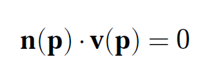
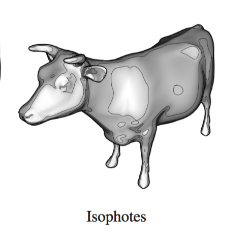
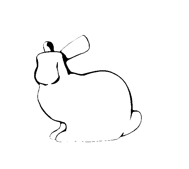
A video of the final output. The first representation is line-drawn silhouette contours, providing a sketch-like rendering of the bunny. The second is the ndotv fragment-shader representation of the silhouette contours with isophote shading. The last section is the silhouette contours from the fragment shader shown alone.
I hope to continue this project, to learn how to render brush strokes and better represent objects using artistic approaches.
In addition to that, all example renderings I found using TriMesh used methods of rendering that were linked to older versions of GLSL, passing vertices and data directly to be rendered, rather than in buffers to shaders. These did not use shaders at all, as far as I could tell, and therefore left me very frustrated in trying to figure out how to adapt this to use the shaders I needed. In the end, I ended up passing the TriMesh data (vertices, normals, etc) directly to the shaders using buffers, similarly to how Shape does. Given the chance to go back, I would have taken more time to gain familiarity with TriMesh.
Another problem I encountered is the support for GlLineWidth(). In general this function is used to define the line width that is drawn when using GlDrawArrays. However, the implementation and support for this varies based on machine and setup, and the actual support for maximum width is extremely variable. It so happened that on my setup, the support was limited to a line width of 1 pixel, making representations of "pencil lines" much harder, and the resulting lines drawn can be hard to see.