Description
The goal of this project was to emulate some of the old point & click games from the 90's, such as Indiana Jones and the Fate of Atlantis and The Dig. These games were created by defining "walkable areas" on top of a 2d background image.
In CPE 471, the focus is on 3d worlds. Since artists' drawings for game backgrounds are (assumedly) a 2d visualization of a 3d world, the goal of this project is to try to infer the geometry of the "original" 3d world behind the 2d background. Motion occurring in this 3d world would then appear to move as if within the background image. To create the 3d world, the original conception of the project included the ability to clip areas out of the background and move them towards the camera (for moving behind objects), as well as the ability to define non-planar terrains to match the backgrounds.
Implementation
The project was implemented using WebGL in JavaScript, after a brief and frustrating venture into TypeScript. Recreating the project scaffolding of CPE 471 from scratch in a different language proved to be more challenging than anticipated. The tutorials at webglfundamentals.org were very helpful, along with the WebGL tutorial on MDN. MDN's documentation was also vital.
After finally getting a simple "Hello World" of displaying an image in WebGL, one of the challenges was dealing with a flexible aspect ratio. Previous CPE 471 assignments had included code in the perspective setup that scaled the window according to the correct aspect ratio. For this project, however, the goal was a background image that always filled the screen without cutting off any part of the image. To this purpose, I attempted to dynamically scale the image's model-space size according to the correct viewport & image dimensions & aspects. I eventually a version of this working for the background alone (not the sprite), but I ended up forgoing the above for a hard-coded viewport size for the sake of time.
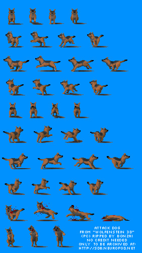
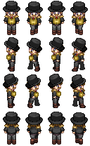
Another challenge in the project was indexing into the sprite. I initially picked a spritesheet of a dog whose individual sprites were not uniformly spaced across the page. It took me a while to figure this out and to switch to a different spritesheet whose sprites were all the same size and uniformly laid out in a grid. This made it simpler to find the sprite frames:
One of the nice things about drawing images in WebGL in comparison to OpenGL is that the Browser DOM already has the ability to load images in a variety of formats and WebGL's texImage2D() takes a JavaScript Image object as an argument. However, the resolution of urls into images is not synchronous in JavaScript, so that had to be handled asynchronously.
One thing I learned is that the rate (in frames per second) of sprite motion does not necessarily match the sprite's animation. With only 4 frames in each of my sprite's animations, I had to define a FPS rate for the sprite's animation itself, while allowing the sprite's motion to happen at the global redraw FPS.
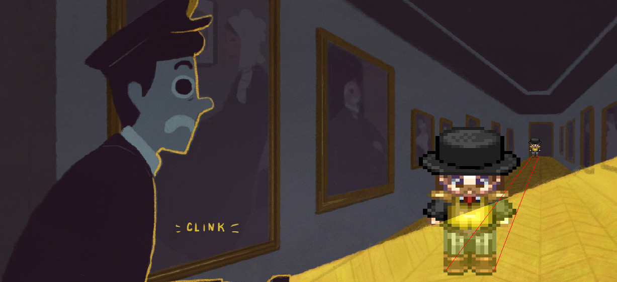
After getting the sprite to animate, and placing it in the 3d world, another hurdle I faced was displaying the sprite in the 3d world without skewing the image. I tried a variety of different things with varying success, but I finally succeeded to by passing to the vertex shader the sprite's centerpoint in model space (in my case it was always (0, 0, 0)), and using that in the perpective matrix multiplication so that all perspectivized X & Y values are based on the same depth. Excerpt from my sprite's fragment shader:
vec4 cameraSpriteCenter = uV * uM * vec4(uSpriteCenter, 1.0);

vec4 cameraPos = uV * uM * vec4(aVertPos, 1.0);

//When calculating the "perspectivized" x & y values, use the same
//z values for all points on the sprite so that the spite doesn't skew
vec4 perspectivePos = uP * vec4(cameraPos.xy, cameraSpriteCenter.z, 1.0);

gl_Position = vec4(perspectivePos.xy / perspectivePos.w, cameraPos.z, 1.0);
I later realized that this was called "billboarding", and I probably could have looked it up if I had looked through the notes of topics Professor Wood gave me to google.
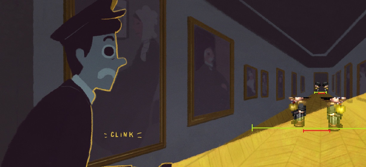
I added the triangle of light to make the image look nicer and because it wasn't difficult. I used the barycentric coordinate calculation from program 1 to determine if points were in the triangle
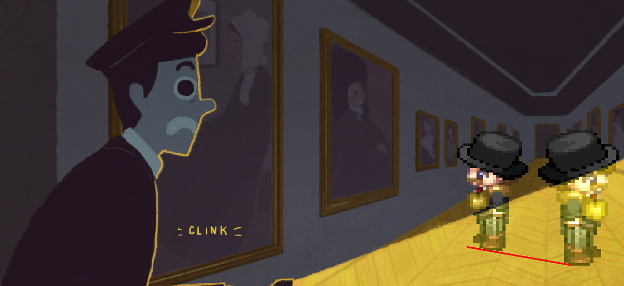
The final challenge in this project was "inferring" the correct 3d world to match the image. I decided to start with something easy and do a flat terrain of y=0, setting the view matrix (eye position, lookAt position, and up vector) in such a way as to make the plane align with the floor in the picture. I also defined minimum and maximum x & z values for this area. However, as seen below, I was never able to perfect the alignment with the image. I had chosen NOT to try and draw the plane (as a transparent grid) in order to make my goals more acheivable and to save time, but after struggling to get the motion of the sprite to match the image, I finally realized that trying to position the plane of the floor without seeing what I was doing wasn't working. By that point I was out of time. While I do think I got it fairly close, it is still not correct. In particular, the walkable area at the far end of the hallway fills the hallway in the image, but at the near end of the image the walkable area is only about 2/3 of the hallway's width:
I have considered continuing on this project for fun, and I think—as I mentioned above—that the next step would be to draw out the flat terrain as a grid of semi-transparent lines that could be toggled on and off. This would allow me to better see how the geometry was lining up. I believe that after defining a grid like this, extending the code to support non-planar terrains would not be too much more effort. Another helpful addition would be some buttons or keys on the page to change some of the world setup parameters like the eye position, look-at position, up vector, terrain boundaries, etc.
Attribution
Helpful Tutorials
Graphics libraries
- Sylvester - A JavaScript matrix library
- glUtils.js - A helper library used in MDN tutorials
Art
- Background from "Heist" by Olivia Huynh
- Man sprite from Steampunk collection by Sithjester
- Dog sprite from "Wolfenstein 3d" and obtained here
Other libraries
- Bootstrap - for the header and this page
- require.js - module/dependency management
- Q - async library
- underscore.js - js utilities library
- RxJS - event handling, definitely overkill
- Kibo - keyboard event handling
- Spin.js - loading spinner