Light gets to the eye by being transmitted from many light sources and bouncing until it reaches the eye. Computationally, this is a very slow process, so we attempt to estimate this by treating light as a collection of rays and tracing backwards. Starting at the eye, cast lighr ays from the eye, and follow the paths of bounces and bends until reaching a boundary condition or a light. This program has two boundary conditions: a number of recursions limited by altering the #MAXBOUNCE define, and a max distance for a light ray.
The first step in writing a raytracer for this project was being able to create scenes by parsing a limited subset of the povray scene specification. At this time, the project supports spheres, planes, lights, the camera, material finish and pigment, and object translation.
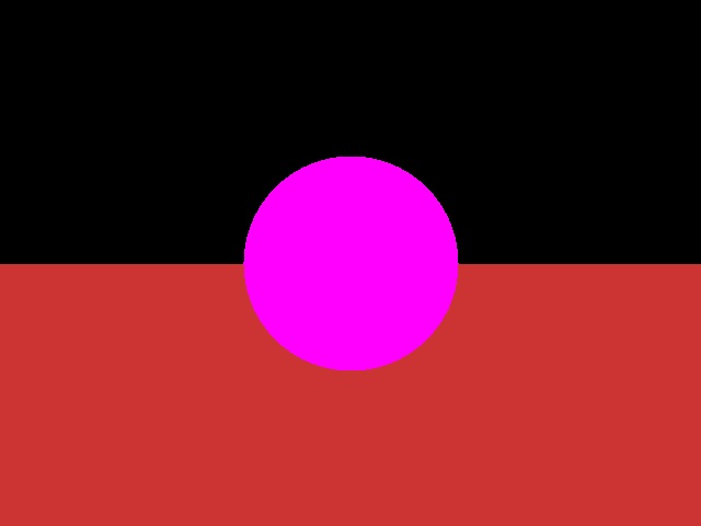
Spheres and planes are examples of GeometricObjects, and therefore they inherit the base GeometricObject class, which defines a number of properties common to all objects, such as position and material. Each class must define its own intersection method. This method reports success of intersection as well as the depth at which the intersection occurred from the origin of the ray. Also, each object needs its own normal method, which gives the normal to a surface based on an input vector. Initially, to ensure intersection was working and that the depths were correct, I flat rendered a sphere on a plane, as shown.
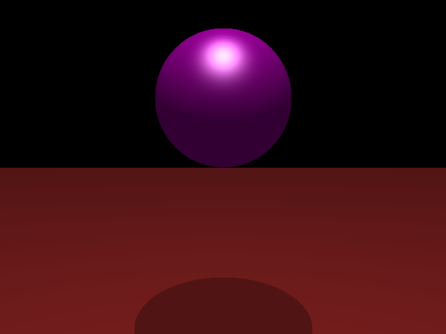
With intersections working the scene needed to be able to calculate how much each light source contributes to each pixel on the ray. Looping through each light source, a vector was created from the point of intersection to the light, then it was normalized. The surface normal is then dotted with this vector, giving the "amount" of the face in direction of the light. If this value is greater than zero, the light contributes to the object by multiplying the dot product amount times the object's diffuse property, the object's color, and the color of the light. Next, the specular component of the light is calculated by finding the bisection vector of the observer and the light source. This vector is normalized and dotted with the surface normal at this point, resulting in a maximum value when the bisection is exactly normal to the face. If the object has roughness, the dot product is raised to a power of 1/roughness. This value is then multiplied with object's specular value and the light's color to give a specular component. Finally, ambient light is added to the object by multiplying the object color times its ambient value and the light color. The result is a Phong shaded model, as shown.
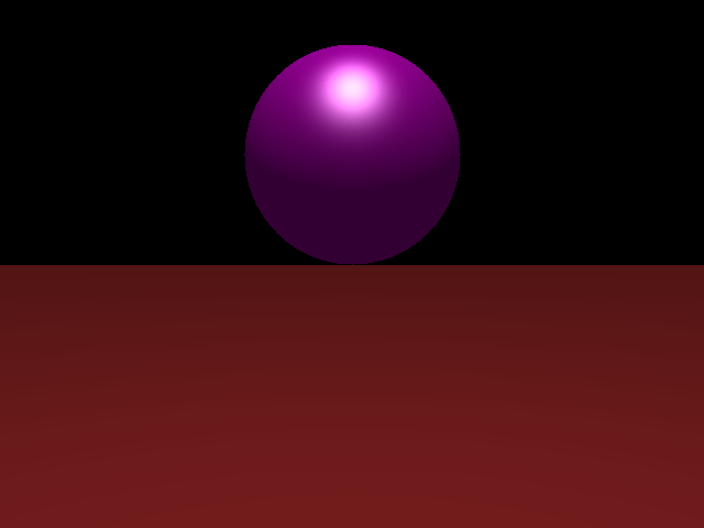
To add shadows to the model, we need to check whether light from a source is able to reach the model or if it is obstructed. If obstructed, only the ambient lighting should be added for that light source. Determining whether a light source is obstructed requires calculating the distance from the point of intersection to the light. Then, a ray is cast from that point towards the light, testing versus each object in the scene in a fashion similar to the initial casting. If the new distance returned is less than the distance to the light, the light is considered obstructed, and that pixel does not get specular or diffuse lighting from the light. The result of this is shown below. Note how the plane is still red from the ambient light, but it does not receiving any diffuse or specular highlighting.
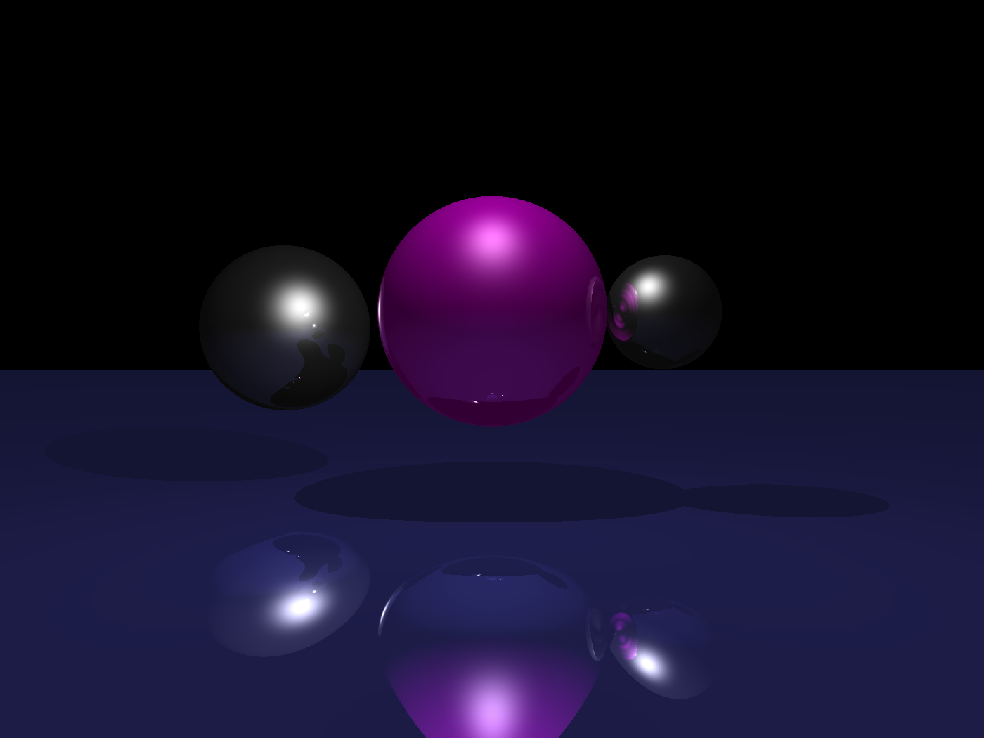
Finally, to show reflection in the scene, a new ray must be cast from the intersection point. This ray's direction is mirrored across the normal and it originates at the intersection point. The returned color values from the recursion are multiplied by the object's reflectivity and added to the overall color for that pixel. Results of this recursion are shown below, click the image for a larger view (the banding is caused by png compression, not raytracing).
You may download the executable and the scene used to generate the above image here.
To run the program, from the command line, execute [RayTracer.exe +Ifilename +Wwidth +Hheight], where filename is the input pov file, width is desired output width, and height is desired output height. Output sometimes takes a while to compute, but it will be saved in the same location as input, with a .ppm extension.
Raytracing has many things one can do, and there's always something else to add. Listed here are those things I did not get to, but would have liked to, and then other items to be added.
The basis of this project is at Cal Tech's 174 site (174 -> 471...Coincidence? I think not!)
There is an excellent tutorial on ray tracing theory at DevMaster (though the code is somewhat obtuse).
This site has a list of alogrithms for various types of intersection (also useful for non raytracing projects).