Overview
The purpose of this project was to create a simple implementation of view dependent texture mapping. Working on this project allowed me to experiment with different real-time rendering techniques in OpenGL, and allowed me to observe the results of different techniques on the quality of the rendered image.
First Steps
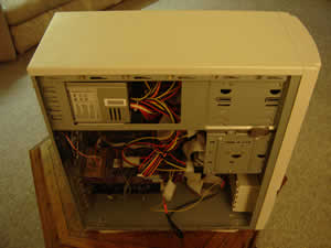
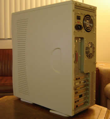
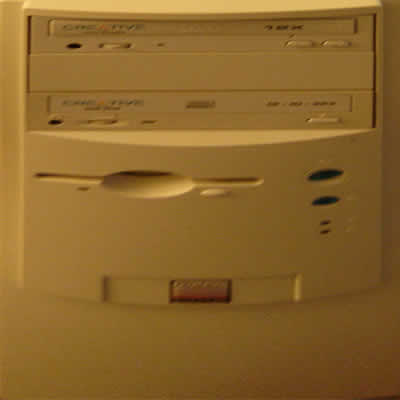
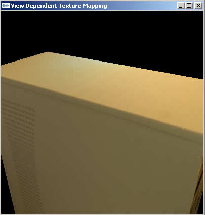
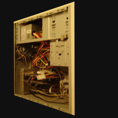
The real-world object that I decided to model was my roommate's computer. The geometry is fairly simple and flat on all sides, except I removed the left panel to expose the inside of the computer. I was curious to see how this complicated depth would affect the rendered image. I took pictures of the computer from multiple angles -- three angles for each side. I did my best to make these angles as close to pure 90 and 45 degree angles as possible. Below are two of the pictures taken.
|
|
I also measured the computer so that I could recreate the geometry in OpenGL with the correct proportions. The first stage of the program was a simple green box (without a bottom), with two triangles per face.
 |
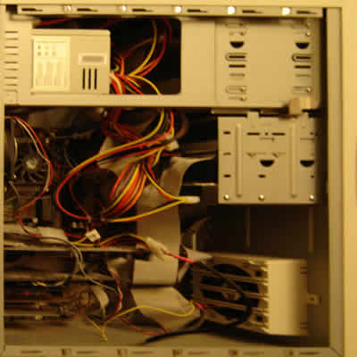
Next, I had to modify the pictures that I had taken so that they would be usable textures. I was not yet willing to delve into projective texture mapping (which I would have to do later), so I pulled each side out of the images and distorted them to fit into either a 512x512 or a 1024x1024 bitmap texture. Examples are shown below.
 |
 |
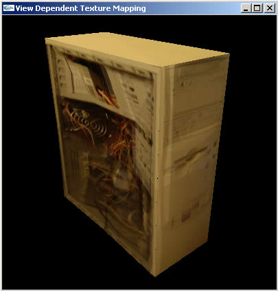
The result was 20 textures (4 for each side). I set up texture mapping in my OpenGL program and set up each side to use its straight-on texture (I really wanted to see something more than green triangles).
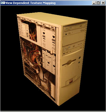 |
It was nice to see what resembled a real computer, but flying around the computer gave you a sense of just how "flat" it really was. Coloring did not change based on the viewing angle, so it didn't look like the computer was lit, but just had some picture pasted onto it. Also, at angles distant from the straight-on angles one could see clear distortion. You can see a good example of what I mean by looking at the bottom portion of the open side of the computer in the image above. These problems would hopefully be solved with view dependent texture mapping.
View Dependence (The Point of the Project)
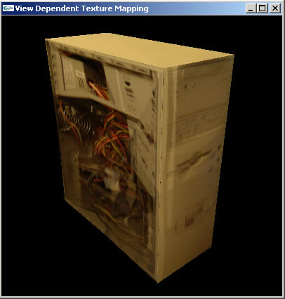
The next step was to actually do the blending of textures based on the view. Blending was done with weights, where the weights are determined by the dot product of the current viewing vector and the vector that describes where the texture image was taken from. I created classes and structures to store information about the computer's sides, their triangles, and the textures associated with them. I first tried to do the texture blending in software, but this turned out to be quite a chore, and it slowed down rendering time significantly, so I devised a solution where each side is rendered four times, one for each texture, and each time it is rendered with an alpha value that represents its weight. The blending is then done in hardware with the only overhead being that the number of triangles sent into the pipeline is now the number of triangles in the mesh multiplied by the number of textures a triangle can represent. This is forgivable for small meshes like this one.
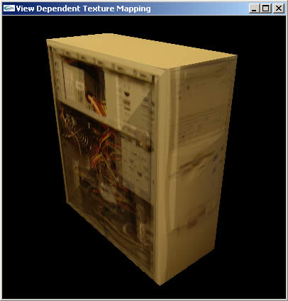 |
Note that the picture seen above doesn't exactly reflect my first version of the view dependent texture mapping code. In the initial code the texture weights were calculated for an entire side, not for each triangle in the side, which is what we see here (different weights are being used for each of the two triangles in the sides). After multiple bug fixes and tack-on's my code was looking very bad, and some of the older code didn't even work anymore (like calculating weights for an entire side), so cleanup of the code included removing the initial VDTM code.
There are some things to mention about these first results. The VDTM does render a more realistic looking image. The lighting seems to change, because the lighting in each image is different. This is very apparent on the top of the computer. Also, mostly flat features like those on the closed side and on the back of the computer looked very nice as the view changed. However, features that were not mostly flat caused "ghosting." Features like the extrusions on the front of the computer or almost everything inside the computer caused ghosting because there was so much of a disparity between them in each image. This disparity was not being represented in the model. Ghosting can be seen in the image above.
To try to remove some of the ghosting, I decided to put some more geometry into the model. I decided I would add functionality to allow the user to control the number of triangles there were in each side, I would create a depth map for the open side, and I would use the depth map to change the depths of the triangles on the open side. I didn't bother with the front side for time reasons.
Each side became two binary triangle trees that were grown to some maximum height. The user could then define how deep to render each side to by pressing the plus and minus keys on the keyboard. This is where the code changed so that each triangle calculated texture weights by comparing the vector from the camera to the midpoint of the triangle with the vector stored with the texture. The results are shown below.
 |
 |
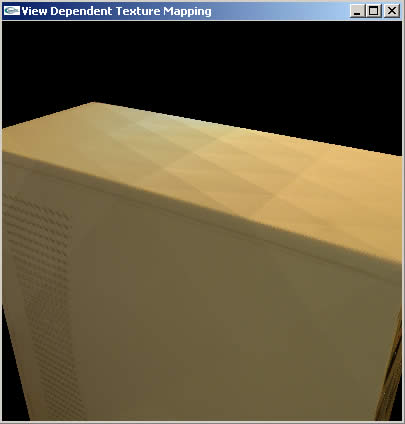
The differences between blending weights is easy to see with low triangle counts and when the camera is close to the computer (the differences between the camera to midpoint vectors are more drastic close up). When we turn up the number of triangles we get a much cleaner result. However, we shouldn't have to turn up the number of triangles just to get a clean result. We could optimize rendering by only rendering as many triangles as are absolutely necessary (whatever the criteria for that would be), and then calculating texture weights at each visible vertex in the mesh. These weights (alpha values) would then be interpolated across each triangle. The result would be a much smoother image. I didn't have time to implement this, I'm sorry to say.
Adding Depth
The next step was to create a depth map for the open side of the computer. I briefly considered doing some kind of stereo correspondence technique to create the depth map for me, but I decided against this idea for fear that It would eat up all of my time (which, in retrospect, seems like it was a wise decision). Instead, I hand painted a depth map.
 |
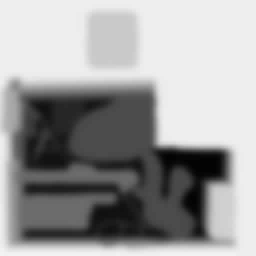 |
The left image is of the original depth map. This original depth map was later modified into the image on the right. The reason for this modification is that the original depth map contained too much detail. This wouldn't normally be a problem, but the detail is not true and exact -- it's hand painted. This caused a tremendous amount of distortion in the final image. The simplified and smoothed depth map still causes distortion, as you will see later on, but not as much. The modified one still causes problems because it is still not perfect. I'm sure that if I had time to implement a stereo correspondence solution I would have seen much better results.
Using the depth map results in the below images.
 |
 |
 |
Just adding depth to the geometry of the open side is not enough, as we can see by looking at the right image above. Texture coordinates are still being supplied as if the surface were flat, and this leads to distortion in the image. The solution to this was to do projective texture mapping. Projective texture mapping was implemented as follows. I made more textures out of my original photographs of the open side, but this time I didn't try to distort them. I only did a few minor tweaks and masked out what I wasn't going to use. An example is shown below.
 |
These images are then projected onto the open side of the computer to determine
the texture coordinates to map each vertex to. This projection is done with:
| 0.5, 0, 0, 0.5 |
| 0, 0.5, 0, 0.5 |
| 0, 0, 0.5, 0.5 | Pproj Vproj Meye-to-world = Teye
| 0, 0, 0, 1 |
The matrix maps from normalized device coordinates [-1, 1] to texture coordinates [0, 1]. Pproj and Vproj are the projection and viewing matrices for our "projector." The product of these matrices is created in OpenGL by initializing the texture matrix to the identity matrix, performing a translate and a scale on the matrix using values of 0.5, and applying gluPerspective and gluLookAt to the matrix. The last component, Meye-to-world, is a matrix that undoes the world-to-eye transform done on the model-view matrix. This is so that we can talk about our projected texture in world coordinates.
Using projective texture mapping we get less distortion than we had before, and the computer looks nicer when flying around it. The insides actually seem to have depth now (because they do). Remember, though, that the depth map is not perfect, so there is still some pretty obvious distortion.
 |
Adding depth to the open side presented one more new problem that took a while to come up with a clean solution for. The depth test had to be disabled for blending to work correctly. Without depth testing, some polygons that were part of the open side were showing through the other sides of the computer. This wasn't a problem before, because back-face culling was removing triangles that were obscured by the visible sides. Now not all obscured triangles were back-facing. I tried to develop an elegant solution for this utilizing the stencil buffer. I did work one out, but I soon realized that neither my computer nor many of the lab computers supported stencil testing. I left my stencil test solution in tact, but I also worked out another solution where the open side is drawn first, and then every other side is drawn by first drawing the side in plane black with no blending. This solution works fine as long as the open side is the only side to ever have depth.
Final Thoughts
I'm very happy with the outcome of my work. I think it resulted in a very nice looking representation of my roommate's computer. There are a number of improvements that would benefit this project, most of which I have already mentioned above. These include depth maps computed via stereo correspondence techniques, applying depth maps to the front face of the computer, and interpolating texture weights across the triangles.
These are all things that I feel confident that I could do if I had more time. However, I feel I should point out that a great deal of my time was spent debugging, tweaking, then debugging some more. Allot of time was wasted on "learning." For example, I "learned" that OpenGL does not use the provided normals for back-face culling, but instead calculates its own normals. Also, I "learned" that my video card doesn't have a stencil buffer, and OpenGL does nothing to warn me of that fact when I try to utilize the stencil buffer.
To wrap up, I found this to be a very informative (though, at times frustrating) exercise. I enjoyed the fact that the product of my work was a real-time rendering that oooh-ed and aaaah-ed both myself and friends. It was also useful for weighing the pros and cons of using view dependent texture mapping for real-time applications, and thinking about how it could be done, and how it could be done better.