Geometry Images: Cutting Algorithm Walkthrough + Rendering Walkthrough Using A Normal Map With Optional Culling
Download: Executable + Sources
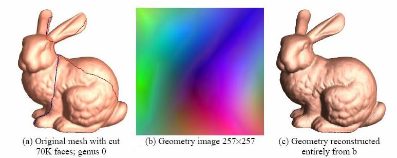
Surface geometry is often modeled with irregular triangle meshes. The process of remeshing refers to approximating such geometry using a mesh with (semi)-regular connectivity, which has advantages for many graphics applications. However, current techniques for remeshing arbitrary surfaces create only semi-regular meshes. The original mesh is typically decomposed into a set of disk-like charts, onto which the geometry is parametrized and sampled. In this paper, we propose to remesh an arbitrary surface onto a completely regular structure we call a geometry image. It captures geometry as a simple 2D array of quantized points. Surface signals like normals and colors are stored in similar 2D arrays using the same implicit surface parametrization—texture coordinates are absent. To create a geometry image, we cut an arbitrary mesh along a network of edge paths, and parametrize the resulting single chart onto a square. [Hoppe]
This program creates a cut path for a geometry image in real time. The cut-path edges are color-coded based on the current step in the algorithm. The cut-path is then highlighted on the original mesh when the algorithm is finished. The second part of our program shows the steps for rendering a mesh from a geometry image and a normal map. We show the program stepping through the geometry image pixels and draw the geometry at the same time. Edges can be turned on and off by the user. Once this is done, the user can turn on culling and move a culling box around to cull triangles and also see the results of the quad tree in the geometry image.
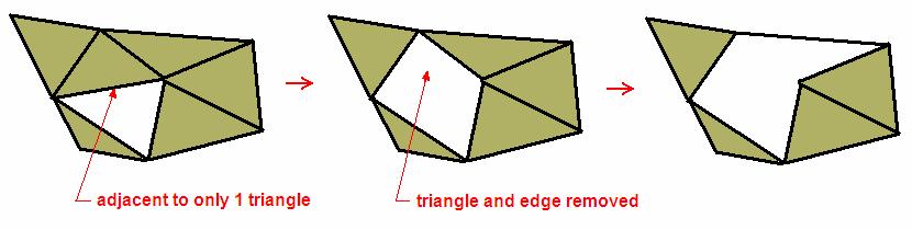
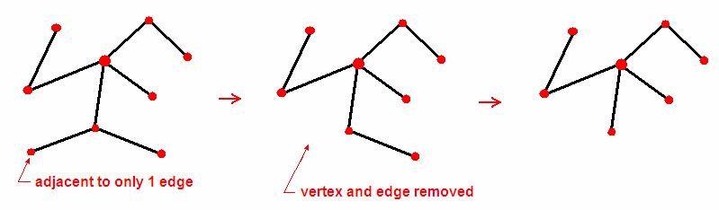
First we start out with an arbitrary manifold mesh. To perform the initial cut in the mesh, begin by removing a random seed triangle. Then find all edges adjacent to only one triangle and remove both (Figure 1). Then find all vertices adjacent to only one edge and remove both (Figure 2).
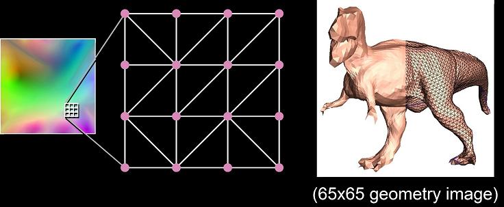
To render geometry images on current hardware, we span each 2×2 quad of grid points using two triangles, by splitting along the shorter of the two diagonals (Figure 3). [Hoppe] We used a normal map of the same size as the geometry image to display more detail. We also implemented a quad tree structure for culling triangles from the mesh (Figure 4).
Right click to access menu.
Left click and drag to translate, rotate, and scale mesh or light.
Program has just been loaded with a 500-triangle gargoyle mesh. Random seed triangle has been removed.
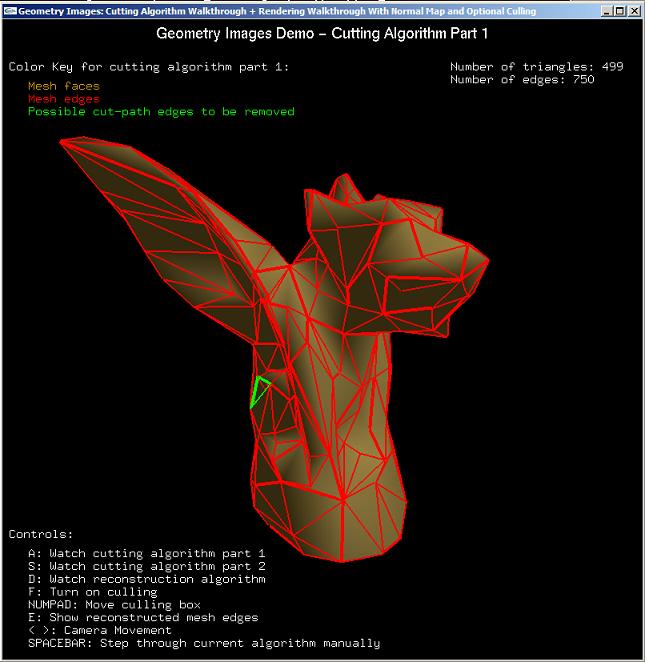
Passed through a few iterations of part 1 of the cutting algorithm. Edges that may be removed are highlighted in green.
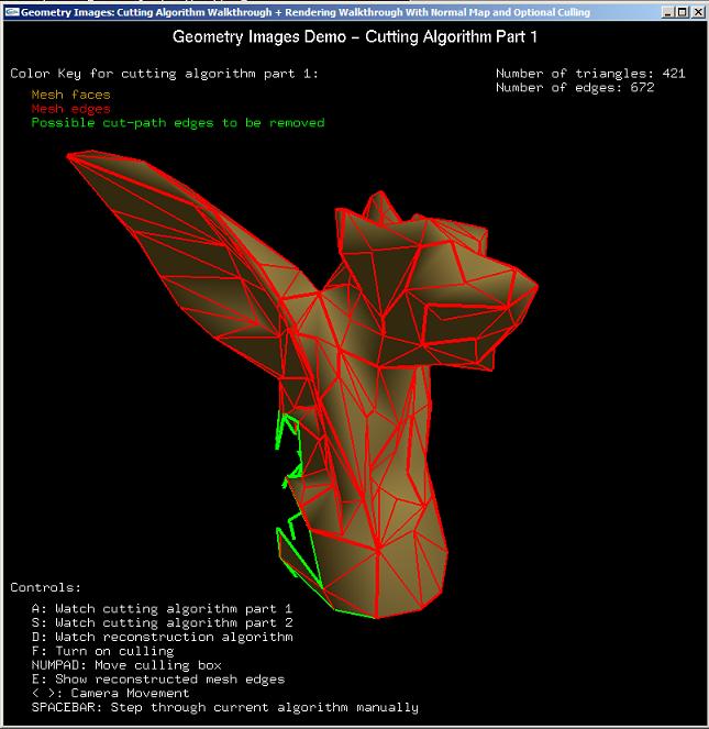
Passed through more iterations of part 1 of the cutting algorithm.
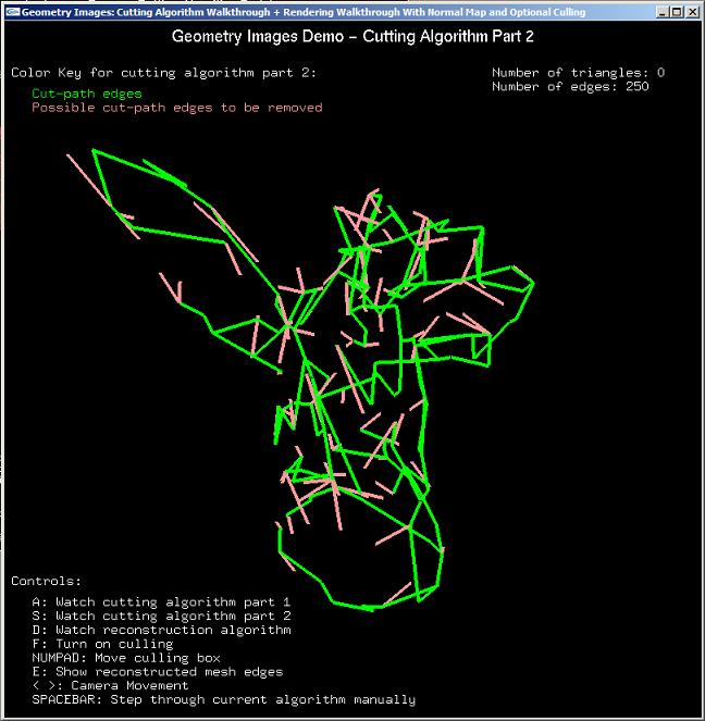
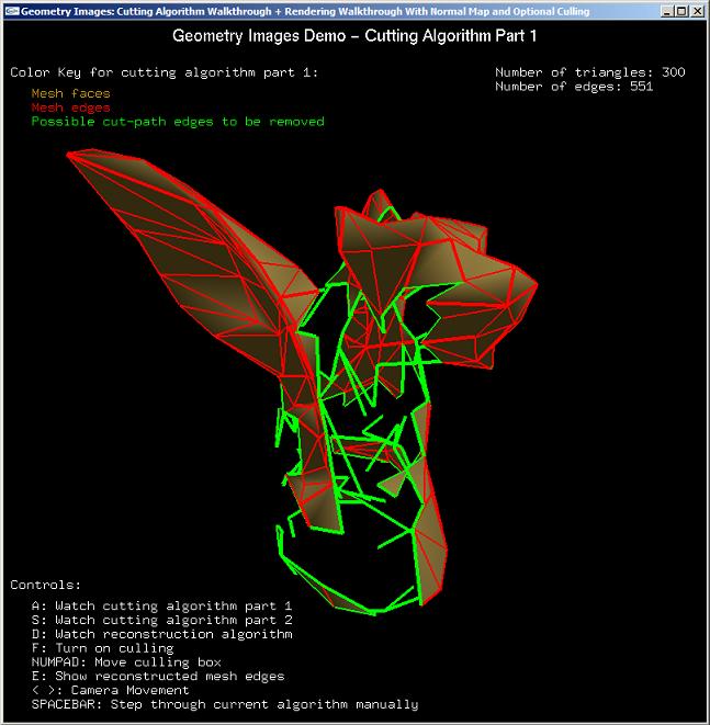
Completion of part 1 of the cutting algorithm. Edges that may be removed for part 2 of the cutting algorithm are highlighted in pink.
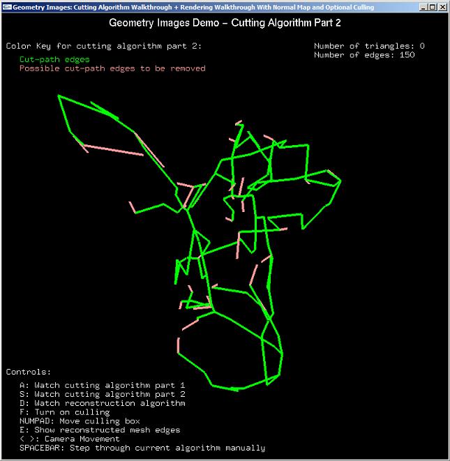
Passed through a few iterations of part 2 of the cutting algorithm.
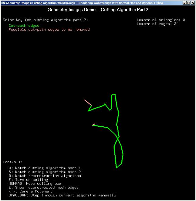
Passed through more iterations of part 2 of the cutting algorithm.
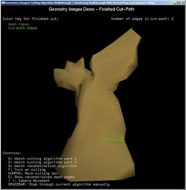
Completion of part 2 of the cutting algorithm. The final cut-path is highlighted in green on the original mesh.
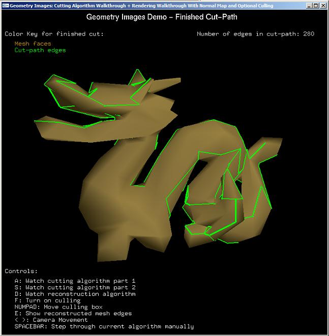
The final cut-path on a 1000-triangle dragon.
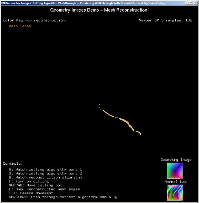
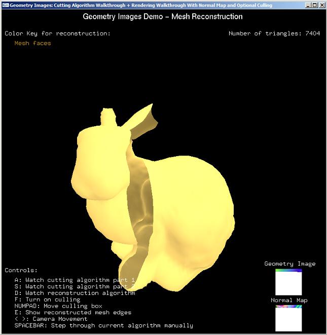
Passed through a few iterations of the mesh reconstruction algorithm using a 65 x 65 geometry image and normal map of the Stanford bunny.
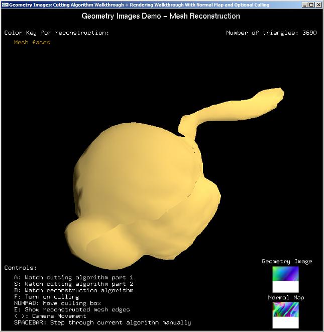
Passed through more iterations of the mesh reconstruction algorithm. Notice the detail captured by the use of the normal map. Also notice the crack on the mesh caused by lossy image compression.
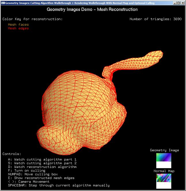
Same mesh with edges overlayed in red.
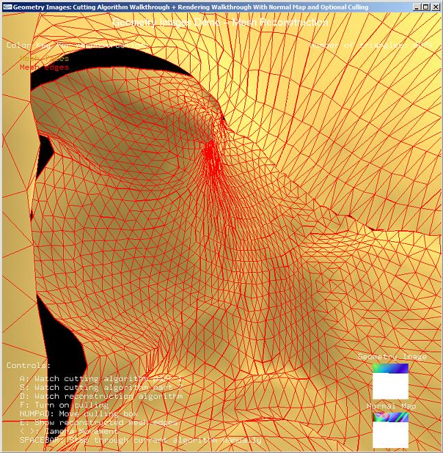
View from inside the bunny during a later portion of the reconstruction algorithm.
Nearing completion of the reconstruction of the bunny.
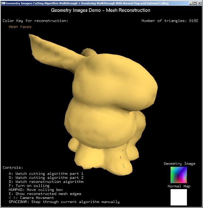
Completed reconstruction of the bunny. There are 8192 triangles created from the 65 x 65 geometry image.
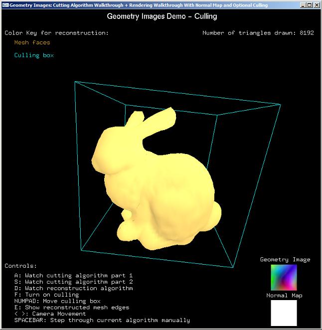
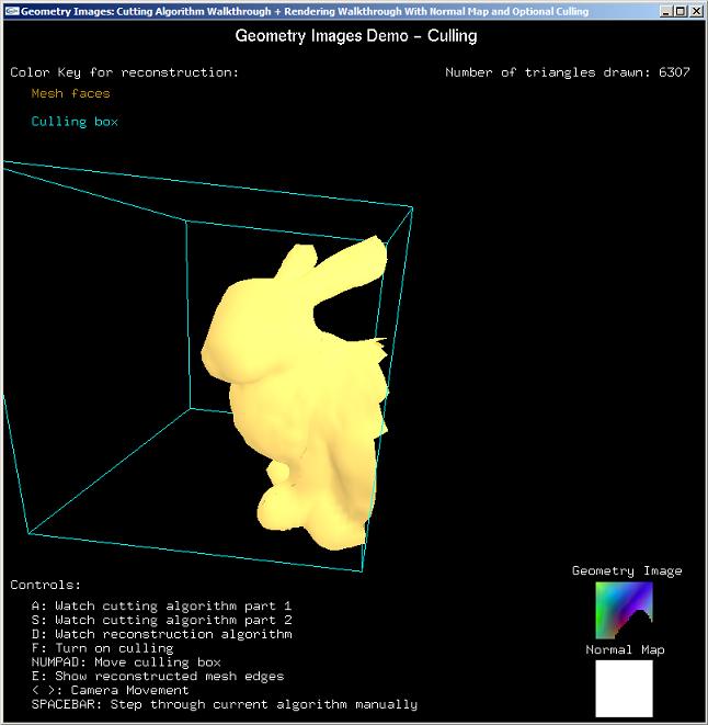
Bunny enclosed in the culling box, drawn in cyan.
Bunny culled on one side. Notice that parts of the geometry image are blacked out via a quad tree traversal, corresponding to the culled triangles.
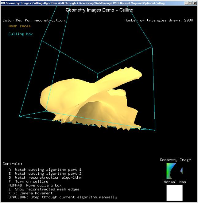
Bunny culled on two sides. Notice how the bunny head is represented mostly by the left side of geometry image.
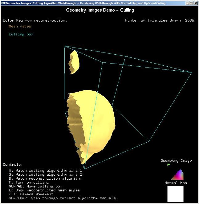
Bunny culled on one side. Notice how the bunny ear is represented by the green pixels on the upper-left of the geometry image.
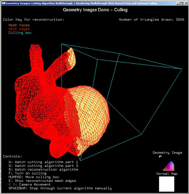
Same culling of the bunny, but with the full reconstructed mesh edges shown in red.