Thin Plate Spline Blended 2D Panoramas
by Bryan Clevenger
What are Thin Plate Splines?
Thin plate splines are control points on a surface that are used to link to separate images together. Seen below, each TPS is represented by a yellow dot, with its index number in the middle:
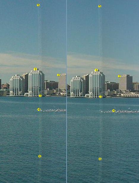
Each dot (or TPS) represent the same spot in both of the two pictures. Using this information, it is possible to compute a transformation from one image to the other, and from there create one blended image.
Why is this important/useful? Can’t you just move one picture over to the left by x pixels?
Sure. You could… But when using a camera each picture is subject to warp around the edges because of the lenses curvature. The warp varies based on the camera and focus difference. Simply grafting one picture onto the other using strictly affine transformations can make this apparent. The benefit of using Thin Plate Splines is that the computed transformation provides the same affine transformation, as well as non-affine transformations to help account for this warp.
What does that mean? Simple: your blended picture comes out much cleaner.
Running the program:
First, ensure your JVM has adequate heap memory to load and manipulate several images. The standard command line argument to increase heaps size is: -Xmx###m where ### is the number of MBs to give the JVM. Personally, I run the program with -Xmx1024m.
Tab 1. Selecting your images
At the moment, the blender only works on 2 images, and blends the right one into the left one.
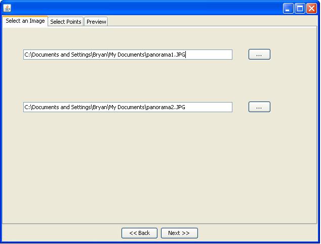
The top file will be the left, and the bottom will be the right. The program expects an absolute path, and to use a file chooser just select the corresponding button.
After selecting two valid (non-gif!) image files, press next.
Tab 2. Selecting the control points
On the next tab, left clicking on an image will add a control point, and right clicking on a control point will remove that control point.
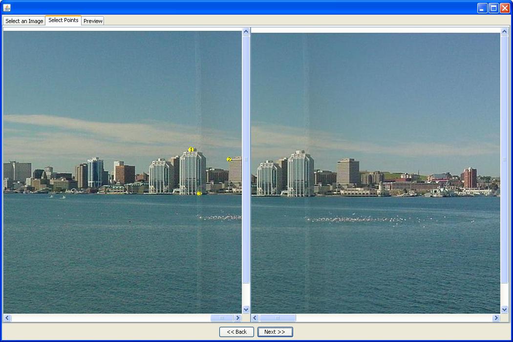
Additionally, if it’s useful to zoom in/out to select your points you can shift-scroll on the image. (Warning: this can lead to massive recalculation, and scroll wheels can be sensitive. Be careful when zooming in!). It’s important to not that the more control points, the more accurate the warp will be and that each side must have the same number of control points since each point represents a “corresponding” point on the two images. After at least 3 (minimum) points are selected on each tab, press next.
Tab 3. The Preview
Moving to this tab, you may think the program has hung; give it a
moment and watch the console for out of memory errors. This can be a real
memory hog, especially if you use more control points. The blended picture
should be displayed:
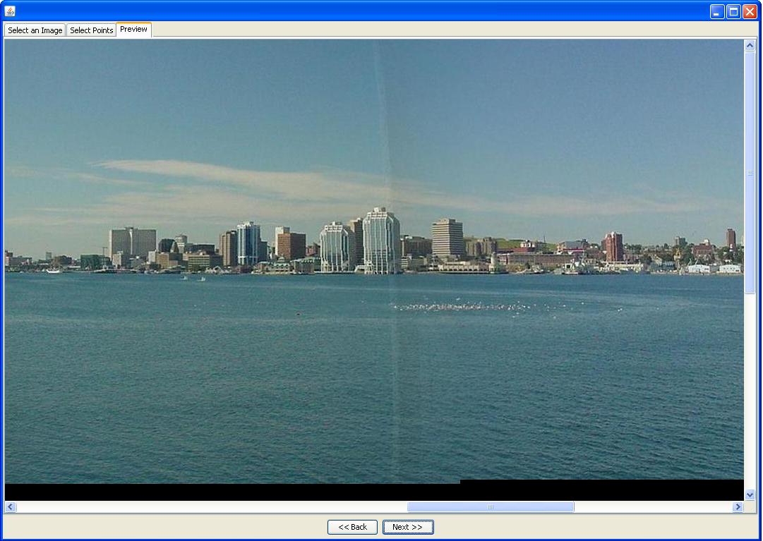
To get a sense of the accuracy of the warp, the above was done with 5 control points. Look at the cloud and the windows in the center building. Make not that the line running down the middle was already apparent in both pictures, and as such would not be removed.
The important part of this warp has been left out though. To really understand why TPS warping is superior, you need to look at the right edge of the new picture:
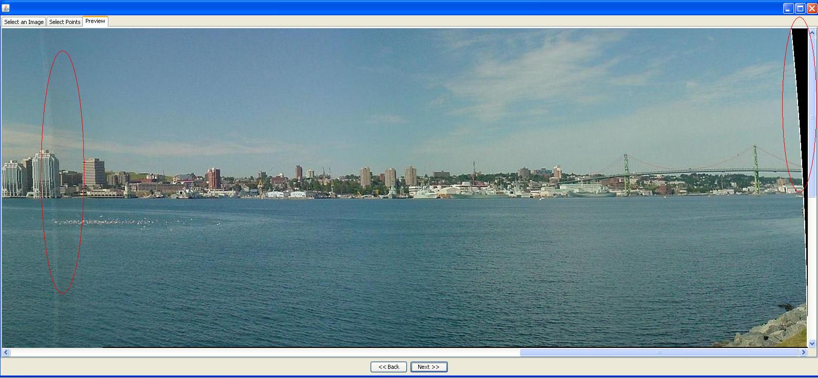
Note the two red circles. On the left is the blended area. On the right is where the edge of the picture has been pulled in at the top. The picture has been bent in order to create a better blend!
Executable Jar:
PanoramaBlend.jar
References:
http://elonen.iki.fi/code/tpsdemo/