-
Adhere to the specification.
-
Any deviation from the specification must be recorded and approved in a
Specification Change Order (SCO).
-
The specification plus SCOs form a binding contract between the
customer and the design team.
- No changes to specification can be made without consulting with the customer and completing a signed SCO.
-
Any deviation from the specification must be recorded and approved in a
Specification Change Order (SCO).
-
Achieve design quality goals:
-
Traceability -- elements of the design trace back to corresponding
elements of the specification.
-
Modularity -- elements of the design are organized into logically
cohesive modules.
-
Portability -- the design is sufficiently general that it can be
implemented on a variety of platforms and a variety of (related) programming
languages.
-
Maintainability -- the system is designed such that it can be easily
repaired and enhanced.
- Re-usability -- where appropriate, modules are designed to promote their reuse in other (future) designs.
-
Traceability -- elements of the design trace back to corresponding
elements of the specification.
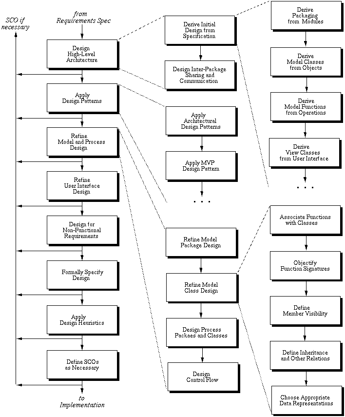
Figure 1: The 307 design process.
and 2).
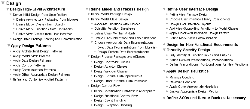
Figure 2: Design Process Fully Expanded.
-
Design High-Level Architecture.
-
The step starts by deriving the high-level architecture of the program from the
requirements model constructed in the Specify
step.
-
The modularization defined for the structural model is carried forward into the
packaging of the program design.
- This enforces traceability between the abstract specification and the corresponding architectural program design.
-
The modularization defined for the structural model is carried forward into the
packaging of the program design.
-
The high level architecture of a program is defined in terms of data classes
and computational functions.
-
These are derived, respectively, from the objects and operations of the
abstract requirements model.
-
The program classes and functions derived directly from the requirements model
constitute the model portion of the design.
- The program classes derived directly from concrete user interface are the view portion of the design.
-
These are derived, respectively, from the objects and operations of the
abstract requirements model.
-
The step starts by deriving the high-level architecture of the program from the
requirements model constructed in the Specify
step.
-
Apply Design Patterns.
-
Once the top-level design elements are derived from the requirements
specification, software design patterns are applied.
-
A design pattern is a pre-packaged piece of design, based on experience that
has been gained over the years by software engineers.
-
High level design patterns can be used to improve the software architecture,
which entails how the major software components relate to one another and
communicate.
-
A widely-used design pattern for end-user software is Model-View-
Process (MVP).
-
The MVP pattern organizes the design into three major segments:
-
the Model is directly traceable to the abstract functionality defined
in the requirements model, and is independent of the concrete end-user
interface;
-
the View segment of the design is devoted specifically and solely to
the end-user interface
- the Process segment defines underlying processing support for the model, in particular processing that encapsulates platform-dependent aspects of the design.
-
the Model is directly traceable to the abstract functionality defined
in the requirements model, and is independent of the concrete end-user
interface;
- Other patterns are employed to assist with design of program data, control, and communication.
-
Once the top-level design elements are derived from the requirements
specification, software design patterns are applied.
-
Refine Model and Process Design.
-
The derived, pattern-based design produced by the first two steps must be
refined into a concrete, object-oriented program design.
-
Model package design is refined using object-oriented design principles,
information hiding conventions, and other design guidelines.
-
Derived functions must be associated with specific model classes, along with
other class refinements.
-
The function-assignment step is necessary because the operations of the
functional specification do not necessarily belong to specific objects.
-
In terms of typical nomenclature, functions associated with classes become
class methods, with appropriate adjustment to method signatures based
on object-oriented design concepts.
-
Other necessary design refinements are in the areas of class member visibility,
inheritance, and the selection of concrete data representations.
- In a modern program design, data representations are typically selected from reusable program libraries.
-
The function-assignment step is necessary because the operations of the
functional specification do not necessarily belong to specific objects.
-
Process class design entails determining the underlying processing support that
is necessary to produce an efficient program.
-
To encapsulate platform-dependent data processing, process classes are
interfaced with model classes via controller, adaptor, and wrapper classes.
- These model/process interface classes encapsulate aspects of the program that are specific to specific operating systems, hardware platforms, and external data stores.
-
To encapsulate platform-dependent data processing, process classes are
interfaced with model classes via controller, adaptor, and wrapper classes.
-
An important part of model and process refinement is detailed control flow
design.
-
Dataflow relationships defined in the specification are refined into concrete
procedural or multi-process control flow
- Other important aspects of control-flow design are functional control flow, event handling, and exception handling.
-
Dataflow relationships defined in the specification are refined into concrete
procedural or multi-process control flow
-
The derived, pattern-based design produced by the first two steps must be
refined into a concrete, object-oriented program design.
-
Refine User Interface Design.
-
The fourth step of design is devoted to refining the end-user interface.
-
In the current state of the art, user interface design typically relies heavily
on libraries of reusable interface classes.
-
The class libraries define commonly-used interface elements and layouts.
-
In a Model-View design, the model classes must be refined to support the view
classes, based on the specifics of the user interface.
-
A particularly useful design pattern in this regard is called the
"Observer/Observable" pattern.
- This pattern defines the way in which view classes can be systematically updated in response to changes made by the user to data values stored in the model classes.
-
The fourth step of design is devoted to refining the end-user interface.
-
Design for Non-Functional Requirements
-
Any non-functional requirements that were not modeled in the specification or
are not yet incorporated in the design are dealt with in this step.
- The purpose of this step is to ensure that all system-related non-functional requirements are fully addressed in the design.
-
Any non-functional requirements that were not modeled in the specification or
are not yet incorporated in the design are dealt with in this step.
-
Formally Specify Design.
-
As the detailed program design is established, the design is formally
specified.
-
This entails the precise definition of function (i.e., method) input/output
signatures, followed by the specification of preconditions and postconditions
for all functions.
-
For the model functions derived directly from the specification, the function
conditions are derived directly from the preconditions and postconditions
defined in the derived-from operations.
-
For other model and process functions, preconditions and postconditions are
defined with the same methodology used in the abstract specification model.
- Namely, preconditions are expressions that must be true before function invocation; postconditions must be true after function executions.
-
As the detailed program design is established, the design is formally
specified.
-
Apply Design Heuristics.
-
Various design heuristics (i.e., general guidelines) can be applied throughout
the process of design.
-
Minimizing coupling among program elements aims to reduce the dependency and
communication to only that which is essential
-
Maximizing cohesion means that program elements that are functionally related
are grouped together, without extraneous unrelated elements.
- Other heuristics can be applied, such as controlling the size of various program components.
-
Various design heuristics (i.e., general guidelines) can be applied throughout
the process of design.
-
Define SCOs and Iterate Back as Necessary.
-
During the course of program design, the developer may discover aspects of the
requirements specification that need to be modified or enhanced.
-
In such cases, the designer defines a specification change order that
clearly states the necessary modifications or enhancements.
-
This formalized change order is in keeping with the high-level process
decomposition into problem definition and problem solution phases.
-
As discussed above, the Analyze and Specify process steps comprise the problem definition
phase.
- The Design and Implement steps then comprise the problem solution phase.
-
As discussed above, the Analyze and Specify process steps comprise the problem definition
phase.
-
In this software process, as in a traditional problem-solving process, changing
the problem definition while the solution is underway requires careful
consideration.
- The specification change order codifies this careful consideration in a precise way.
-
During the course of program design, the developer may discover aspects of the
requirements specification that need to be modified or enhanced.
-
The process employs techniques from a number of design methodologies,
including:
-
The UML (unified modeling language) of Rumbaugh, et al.
-
The structured design techniques of Yourdon, et al.
- The MVP (Model-View-Process) technique (aka, MVC -- Model-View-Controller), used originally with the Smalltalk language, and now used extensively in Java designs.
-
The UML (unified modeling language) of Rumbaugh, et al.
-
The process works well for information processing systems with substantial end-
user interfaces, which are the types of systems developed in 307.
-
For other types of system, similar process steps can be used, but possibly in a
different order, and with different domain-specific methodologies.
-
Other major system types include:
-
Realtime systems, such as communications software.
-
Utility systems, such as compilers and operating systems.
- Embedded systems, such as device drivers and process controllers.
-
Realtime systems, such as communications software.
-
One of the problems to be confronted in designing from a formal specification
is the translation from the requirements/specification language into the
design/implementation language.
-
In some cases, specification languages may differ from programming languages,
since there are different forces influencing the design of the two types of
languages.
- In the case of specs written in the first half of 307, the specs are written in a subset of Java, which is the same as the 307 design and implementation language.
-
In a word, design is an abstraction of the implementation.
-
The idea of abstraction is that things get left out.
-
The simplest definition of what implementation-level detail gets left out of
the design is the sequential code bodies of methods.
-
This by itself is an over simplification of the design process.
- There are several levels of design abstraction, each one leaving out more information.
-
The idea of abstraction is that things get left out.
-
The levels of design abstraction from highest to lowest can be broken down as
follows:
-
Packaging Design
-
The highest level of architectural design abstracts out everything but the
largest modular units, which in Java design terminology are the packages.
-
We give names to the packages, describe them, and discuss abstract
communication and dependencies between them.
- We define the separate executable components of the program, including separate application programs and servers.
-
The highest level of architectural design abstracts out everything but the
largest modular units, which in Java design terminology are the packages.
-
Abstract Class Design
-
Classes are added as components of the packages.
- We name and describe the classes but do not define their contents or inheritance relationships.
-
Classes are added as components of the packages.
-
Mid-Level Class Design
-
We add methods and data fields to classes.
-
We name and describe the methods and fields, but do not define method
signatures or concrete data representations for the fields.
- We define inheritance relationships among classes.
-
We add methods and data fields to classes.
-
Detailed Class Design
-
We add full input/output signatures to methods.
- We select concrete data representations for data fields.
-
We add full input/output signatures to methods.
-
Functional Design
-
We add pre- and postconditions to all methods.
- We define control flow among methods using function diagrams or equivalent notation.
-
We add pre- and postconditions to all methods.
-
Packaging Design
-
At any and all of these levels, we can apply suitable design techniques
(a.k.a., design patterns), when and if such patterns exist.
-
For us, we're going to start with the following two patterns, the one of which
is quite general and widely used, the second of which is rather specific to our
particular kind of software.
-
The "Model/View/Process" pattern, addressing design abstraction levels 2
through 5.
- The "Information Processing Tool" pattern, addressing design abstraction level 1.
-
The "Model/View/Process" pattern, addressing design abstraction levels 2
through 5.
-
The building architect Christopher Alexander defined a design pattern as
follows:
"Each pattern describes a problem which occurs over and over again in our environment, and then describes the core of the solution to that problem, in such a way that you can use the solution a million times over, without ever doing it the same way twice."
-
This same concept applies to software as well as it does to buildings, with
appropriate change in notation.
- For software, the notation is software design diagrams, templates of software code, and step-by-step descriptions of pattern application.
-
The Model/View/Process (MVP) pattern is used to separate the core processing of
an application from the concrete GUI and underlying support processing.
-
The Model is the part of the design that is directly traceable to the abstract
specification, representing the core processing.
-
The View consists of concrete GUI processing
- The Process is the underlying support processing that provides the functionality needed by the model to get the work done efficiently.
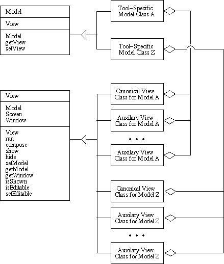
Figure 3: MVP Pattern.
-
The Model is the part of the design that is directly traceable to the abstract
specification, representing the core processing.
-
There is a direct correspondence between each model class and one or more
companion view classes.
-
Typically, there is a standard, or canonical view class that presents
a complete interface from the model to the user.
-
There may be additional auxiliary views that show selected portions a model,
presented in ways that are helpful to the user.
- In all cases, both model and view classes are always directly traceable to the requirements specification.
-
Typically, there is a standard, or canonical view class that presents
a complete interface from the model to the user.
-
Figure 3 is a general diagram of MVP.
-
The figure shows the data members and methods for the abstract Model and View
classes.
- For 307, these classes are defined in the 307 Java class library.
-
The figure shows the data members and methods for the abstract Model and View
classes.
-
This pattern is used to layout the high-level packaging of a software
application.
-
It is used in conjunction with both the Derive-from-Spec and MVP patterns.
-
The pattern applies to the of the kind of applications we are building in 307.
-
These are programs that perform a specific set of information-processing tasks,
under the continued direction of a human user.
- The the application uses a graphical user interface of the form that has become common in computer operating environments, with a menu-based and/or toolbar- based top-level UI.
-
These are programs that perform a specific set of information-processing tasks,
under the continued direction of a human user.
-
In this pattern, each major functional grouping is organized into a pair of
packages, one for model classes, the other for view classes.
-
These functional packages are contained in a top-level package that houses the
top-level model class for the tool itself, as well a Main class that
contains the top-level main method.
-
A top-level view package contains the top-level view classes for the tool,
typically a menubar and zero or more main tool windows.
-
Figure 4 is a high-level diagram of the pattern.
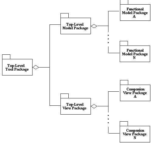
Figure 4: IPT pattern.
-
These functional packages are contained in a top-level package that houses the
top-level model class for the tool itself, as well a Main class that
contains the top-level main method.
-
When applied in conjunction with the Derive-from-Spec pattern:
-
Each functional model package is derived from a specification module.
- The view packages and the top-level application package are new to the design.
-
Each functional model package is derived from a specification module.
-
Overall, this pattern uses information from the following sources:
-
The organization of the end-user requirements scenarios, in which each
major section of the scenarios is a candidate for a package in the design.
-
The organization of the top-level GUI, in which each major unit in the
UI is a candidate for a package in the design; "major units" of the UI include
pulldown menus, free-floating toolbars, other well-delineated components of the
interface.
- Modular organization of the Java model, in which each module (or separate .sl file) is a candidate for a package in the design.
-
The organization of the end-user requirements scenarios, in which each
major section of the scenarios is a candidate for a package in the design.
-
Last quarter we looked at the requirements specification for a Calendar Tool
application that is similar in size and scope to your 307 projects.
- We'll continue this quarter with the design and implementation of the Calendar Tool.
-
There are seven modules in the Calendar Tool specification, one for each of the
six functional command categories (as shown on the pulldown menu), and one for
the underlying calendar database:
-
File -- file command processing
-
Edit -- edit command processing
-
Schedule -- calendar item scheduling
-
View -- viewing calendars and lists
-
Admin -- managing the user and group databases
-
Options -- managing user options
- CalDB -- the calendar database for all registered users
-
File -- file command processing
-
Applying the derivation pattern, we get seven model packages for these.
-
Applying the IP tool pattern, we add a top-level tool package, and companion
view packages for each model
-
A diagram is shown in Figure 5.
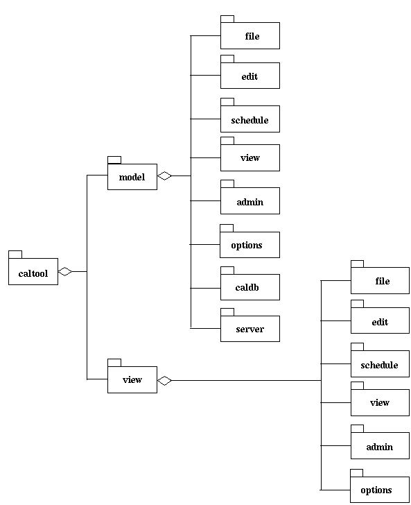
Figure 5: Calendar Tool packages.
-
It is noteworthy that there are no companion UI packages for the CalDB and
Server packages; these are processing packages that have no direct user
interface.
-
A derived version of the top-level tool class is the following, which is
defined in the file
implementation/source/java/caltool/CalendarTool.java:
package caltool.model;

import caltool.view.*;
import caltool.model.file.*;
import caltool.model.edit.*;
import caltool.model.schedule.*;
import caltool.model.view.*;
import caltool.model.admin.*;
import caltool.model.options.*;
import caltool.model.help.*;
import caltool.model.caldb.*;
import mvp.Model;

/****
 *
 * Class CalendarTool is the top-level model class for the regular-user
 * Calendar Tool program.  CalendarTool has references to the functional model
 * classes of the tool: File, Edit, Schedule, View, Admin, Options, and Help.
 * There is also a reference to the CalendarDB class that houses the tool's
 * major data bases.
 *                                                                          <p>
 * Functionalitywise, all of the model classes are autonomous units.  They each
 * do their own work as invoked by the user.  All that this top-level class
 * does is to construct the work-doing model classes and set up the initial
 * state of the tool when it is invoked from the outside operating system.
 *                                                                          <p>
 * See also the companion view class <a href= "caltool_ui/CalendarToolUI.html">
 * CalendarToolUI. </a>
 *                                                                          <p>
 * @author Gene Fisher (gfisher@calpoly.edu)
 * @version 13apr15
 *
 */
public class CalendarTool extends Model {

    /**
     * Construct this with the given companion view.  Call the submodel
     * constructors.  Initialize the start-up state based on default options
     * and command-line arguments.
     */
    public CalendarTool(CalendarToolUI calToolUI) {

        /*
         * Call the parent constructor.
         */
        super(calToolUI);

        /*
         * Construct and store the submodel instances.  Note that the
         * CalendarDB is constructed before the File so the latter can observe
         * the former for changes.
         */
        caldb = new CalendarDB(null);
        file = new File(null, caldb);
        edit = new Edit(null);
        schedule  = new Schedule(null, caldb);
        calView = new View(null, caldb);
        admin = new Admin(null);
        options = new Options(null);

        /*
         * Set up the initial state of the tool.
         */
        initialize();
    }

    /**
     * Implement the exit method to pass the buck to file.exit().  Per set up
     * performed in the companion CalendarToolUI view, this method is called
     * when the user closes the top-level menubar window, e.g., via the window
     * manager close button.
     */
    public void exit() {
        file.exit();
    }

    /** Return the File model. */
    public File getFile() { return file; }

    /** Return the Edit model. */
    public Edit getEdit() { return edit; }

    /** Return the Schedule model. */
    public Schedule getSchedule() { return schedule; }

    /** Return the View model. */
    public View getCalView() { return calView; }

    /** Return the Admin model. */
    public Admin getAdmin() { return admin; }

    /** Return the Options model. */
    public Options getOptions() { return options; }

    /** Return the Help model. */
    public Help getHelp() { return help; }


    /*-*
     * Protected methods
     */

    /**
     * Set up the initial state of the tool, based on default option values and
     * command-line arguments, if any.  Details TBD.
     */
    void initialize() {}


    /*-*
     * Data fields
     */

    /** File-handling module */
    protected File file;

    /** Basic editing module */
    protected Edit edit;

    /** Scheduling module */
    protected Schedule schedule;

    /** Calendar viewing module */
    protected View calView;

    /** Calendar administration module */
    protected Admin admin;

    /** Tool options module */
    protected Options options;

    /** Tool help module */
    protected Help help;

    /** Calendar database */
    protected CalendarDB caldb;

}
-
Figure 6 shows a class diagram for the key classes in the design of the
Milestone 6 example.
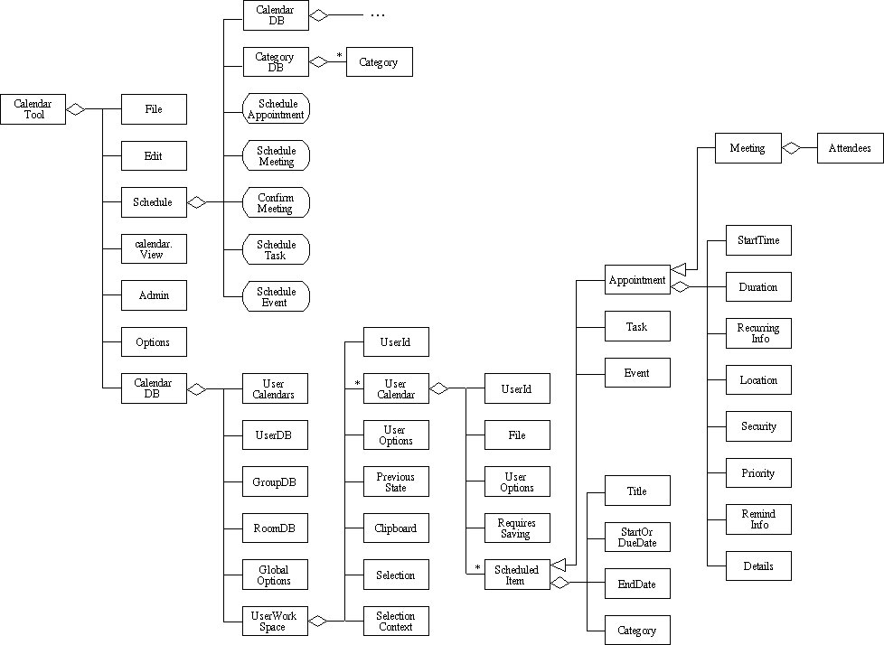
Figure 6: Class diagram for Calendar Tool design in Notes 2.
-
As noted above, the design and implementation for the 307 Milestone 4 example
are at
users.csc.calpoly.edu:~gfisher/classes/307/examples/milestone4
-
The abstract model from which the design is derived was begun in the 307
and is refined into a design specification in theMilestone 4 example
Milestone 6 example
-
The HCI from which the GUI design is derived is in the 307
which is further refined and finalized in the 307Milestone 4 requirements
Milestone 6 requirements
-
As noted above, the design and implementation for the 307 Milestone 4 example
are at
-
In the 307 design, the CalendarTool and its seven components are
derived using the IPT design patter applied to the top-level Calendar Tool GUI.
-
The methods of the Schedule class are a refinement of the abstract
specification, with added information hiding.
- The components of the CalendarDB are a refinement of the specification that is part of the model refinement work of Milestones 5 and 6.
-
CalendarDB.java
-
Traceability to spec is quite direct.
-
This is managerial-style class, as opposed to a data abstraction.
-
It contains references to other major model classes which are themselves data
abstractions.
- CalendarDB has contains no traceable methods.
-
It contains references to other major model classes which are themselves data
abstractions.
-
As with other directly traceable classes, the top-level class comment is
derived directly from description in the CalendarDB abstract model
-
When the spec object descriptions are complete and well-written, use the text
directly.
-
When the descriptions are missing or incomplete, (re)write an appropriately
descriptive text.
- In either case, class comments must be enhanced with additional information, as described in the 307 SOP Volume 2 on Java design and implementation conventions.
-
When the spec object descriptions are complete and well-written, use the text
directly.
- The derived data fields of class CalendarDB trace directly to the CalendarDB spec object, including the comments.
-
Traceability to spec is quite direct.
-
Schedule.java
-
Class Schedule.java does not trace to a spec object, but is rather a
managerial class designed to hold methods that trace to spec
operations.
-
In general, the abstract model spec does not always define objects for the top-
level functional groupings that correspond to the command pulldown menus.
-
This in an example of where the functionally-oriented abstract spec requires
some refinement when translated to an object-oriented concrete program.
-
In particular, methods that are in the Schedule class, were originally
defined in the abstract model's Calendar class.
-
In the concrete design, there are two levels of refinement for the calendar: a
Schedule class that contains the user-level calendar operations, and a
UserCalendar class that contains lower-level implementations of the
calendar operations.
-
The user-level methods communicate with the view, and perform data validation.
- The lower-level methods encapsulate the concrete data structure for the calendar, and provide an efficient implementation.
-
In particular, methods that are in the Schedule class, were originally
defined in the abstract model's Calendar class.
-
In general, the abstract model spec does not always define objects for the top-
level functional groupings that correspond to the command pulldown menus.
-
Class Schedule.java does not trace to a spec object, but is rather a
managerial class designed to hold methods that trace to spec
operations.
-
ScheduledItem.java
- This class traces quite directly to the corresponding abstract model ScheduledItem object.
-
Appointment.java,
Meeting.java, Task.java,
and Event.java
-
These classes also trace quite directly to their corresponding abstract model
objects.
- Note that the inheritance relationships among the abstract objects are retained in the derived Java classes.
-
These classes also trace quite directly to their corresponding abstract model
objects.
-
Date.java
-
Date is a straightforward translation of its abstract model object.
- As the model is refined, this class will likely be replaced with a date representation from the Java library.
-
Date is a straightforward translation of its abstract model object.
-
In 307, the default GUI library is Java Swing; as noted in the Milestones 5-6
writeup, your team may choose to use a different by comparable library.
-
The Swing library is rooted in the package named javax.swing, which
contains many classes and subpackages for building GUIs.
-
Key Swing classes include the following:
- Box -- a simple way to layout GUI components.
- ButtonGroup -- for grouping buttons, particular radio buttons.
- JButton -- a standard command button; used all over the place.
- JCheckBox -- a typical on/off check box.
- JCheckBoxMenuItem -- a menu itme with a check box next to it.
- JColorChooser -- a standard-looking color selection dialog.
- JComboBox -- a pulldown that allows typing too.
- JComponent -- the top-level of the Swing component hierarchy.
- JDialog -- a handy pop-up dialog.
- JEditorPane -- a way to view and edit text, in particular HTML.
- JFileChooser -- a standard-looking file chooser.
- JFrame -- the outermost container for a GUI window.
- JLabel -- a simple piece of text within a GUI.
- JLayeredPane -- a way to layer GUI frames in a 3D stack.
- JList -- a list of GUI components, typically with a scroll bar.
- JMenu -- a pulldown or pop-up menu.
- JMenuBar -- a standard menubar, typically at the top of a JFrame.
- JMenuItem -- an item in a JMenu.
- JOptionPane -- a parent class for a set of standard option dialogs.
- JPanel -- Typically the inner-wrapper of a JFrame, for managing GUI layout.
- JPasswordField -- a way to enter passwords without echoing.
- JProgressBar -- a typical-looking "throbber"
- JRadioButton -- a typical-looking radio button
- JScrollBar -- horizontal or vertical scrollbar, typically in a JScrollPane.
- JSeparator -- spacing in a menu.
- JSlider -- typical-looking slider, typically for numeric input.
- JTabbedPane -- tabbing pane for organizing things like preferences.
- JTable -- a two-dimensional table, with many display options.
- JTextArea -- a simple, unformatted multi-line text area.
- JTextField -- a single-line text field.
- JToggleButton -- an on/off button.
- JToolBar -- a container for buttons that select other tools.
- JToolTip -- roll-over help for tool buttons or menu items.
- JTree -- a hierarchical tree display, in a Windows Explorer style.
-
Key Swing subpackages are:
- javax.swing.colorchooser -- color chooser support classes
- javax.swing.event -- low-level classes representing GUI events
- javax.swing.filechooser -- file chooser support classes
- javax.swing.table -- JTable support classes
- javax.swing.text -- text display and editing support classes
- javax.swing.text.html -- HTML support (there is also XML support)
- javax.swing.text.html.parser -- low-level HTML support
- javax.swing.tree -- JTree support classes
- javax.swing.undo -- simple undo/redo support
-
"awt" stands for the "abstract windowing tools".
-
The classes and interfaces include the following:
- Color -- low-level color support
- Component -- THE most generic GUI component, parent of JComponent
- Container -- THE most generic GUI container, parent of JFrame
- Event -- all the details of a GUI event
- Graphics2D -- the way to draw graphic shapes, e.g., lines, circles, etc.
- GridLayout -- a nasty way to do 2D layout (I like Boxes much better)
- Image -- a GIF or JPEG image
- java.awt.ActionListener -- the way buttons and menu items list for events
-
The list of the Java swing components given above are those that you are most
likely to use in the GUI interfaces for your CSC 307 projects.
-
Figure 7 shows an annotated version of a typical menubar and its menus,
indicating which swing components are used for which pieces.
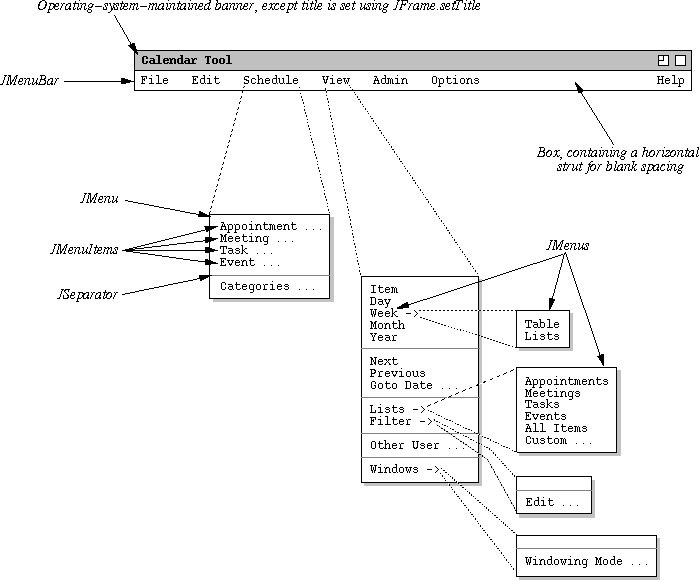
Figure 7: Annotated menus showing swing components used.
-
Figure 8 shows an annotated version of a typical editing dialog indicating
which swing components are used for which pieces.
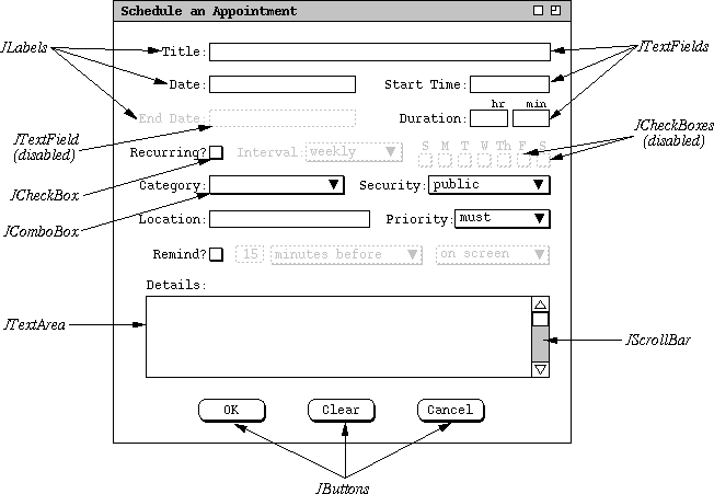
Figure 8: Annotated dialog showing swing components used.
-
Figure 9 shows an annotated version of the editing dialog showing how
components are laid out using Swing Boxes; layout can also be done
using GridBags and other forms of layout managers, but I find these
much more tedious than simple Boxes.
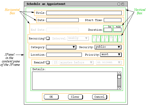
Figure 9: Annotated dialog showing layout using boxes.
-
A standard set of name suffixes is used for view classes in the 307 examples.
-
The suffixes indicate the general usage of a GUI class, as shown in Table 1.
Suffix Example Meaning UI ScheduleUI A top-level view that contains all of the interface components for a companion top-level model. These components are the pulldown command menu and all of the other views that are launched from menu commands. Dialog ScheduleAppointmentDialog A top-level view that allows the user to provide inputs for a single operation. Typically it has OK, Cancel, and Clear buttons. The OK button is used to confirm the operation for which the user is entering the input. Editor CategoriesEditor A top-level view that provides for the editing Has more command buttons than just OK, e.g., Add, Delete. Display MonthlyAgendaDisplay A read-only display, i.e., where no model data are editable. ButtonListener OKScheduleAppointmentButtonListener An event listener for a button or menu item. Panel SchedulingOptionsPanel The internal component of a tiled or tabbed layout. Table 1: GUI Class Naming Conventions.
-
Based on the design patterns discussed in these notes, there is a parallel
decomposition of Model and View classes in a high-level design.
-
The library Model and View classes are at the top of the
inheritance hierarchy.
- Tool-specific model and view classes inherit from these.
-
The library Model and View classes are at the top of the
inheritance hierarchy.
-
To ensure traceability, the high-level class decomposition in the design should
be structurally the same as what we called the functional hierarchy in
the requirements specification.
-
At the spec level, the functional hierarchy was embodied in two forms.
-
For the end user, the high-level UI organization of pulldown menus and dialogs
embodies the functional hierarchy.
- In the formal Spest spec, the package and object structure embodies the functional hierarchy.
-
For the end user, the high-level UI organization of pulldown menus and dialogs
embodies the functional hierarchy.
- When we move to the design level, this very same functional hierarchy should be embodied in the package and class structure.
-
At the spec level, the functional hierarchy was embodied in two forms.
-
The most important issue here is that functional hierarchy makes
sense.
-
The physical embodiments of it are just different views of the same abstract
organization.
-
If the requirements- or specification-level embodiments don't make sense or are
inconsistent, then this should be fixed in the design-level.
-
If we had the time, we'd go back and fix both the requirements and
specification to agree with the design.
- Since we don't have the time to do this in 307, we describe in the SCOs what changes have been made to the design-level hierarchy with respect to the requirements and specification.
-
The physical embodiments of it are just different views of the same abstract
organization.
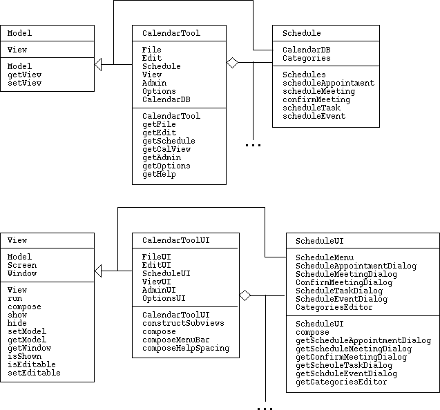
Figure 10: High-level Model/View class diagram.
-
The abstract Model and View classes are the root of the
model/view inheritance hierarchy.
-
Inheriting from these are the top-level model and view classes for a particular
application tool, in this case CalendarTool and
CalendarToolUI.
-
These top-level tool classes in turn have components that are
submodels and subviews, decomposed following the tool's
functional hierarchy.
- Submodels and subviews also inherit from the abstract Model and View classes, since submodel and subview instances communicate directly with one another using the model/view pattern.
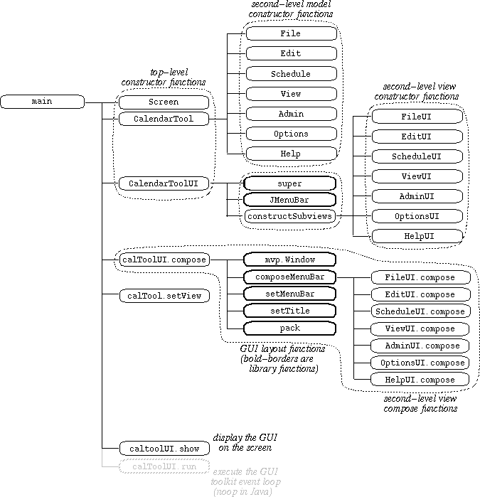
Figure 11: Highest-level function diagram for Model/View application.
-
The first three function calls are to class constructors for the UI screen, the
top-level tool model (CalendarTool) and the top-level tool view
(CalendarToolUI)
-
The call to the Screen constructor constructs and initializes the GUI
screen on which the View functions will display the user interface elements; in
the case of Java, it's a no-op unless the look and feel of the screen are to be
changed.
-
The call to the CalendarTool constructor constructs the top-level
Calendar model, which in turn calls constructors for all subsidiary model
classes and the data objects they require.
- The call to the CalendarMenuUI constructor constructs the top-level elements of the user interface, which in turn calls constructors for all subsidiary view classes and the UI objects they require.
-
The call to the Screen constructor constructs and initializes the GUI
screen on which the View functions will display the user interface elements; in
the case of Java, it's a no-op unless the look and feel of the screen are to be
changed.
-
The call to CalendarToolUI.compose performs all specific details of UI
layout (in the diagram, compose is invoked through the
CalendarToolUI variable named calToolUI).
-
A number of subfunctions are invoked to layout the various UI pieces.
- The functions with bold borders in the diagram are supplied by the Java and 307 libraries.
-
A number of subfunctions are invoked to layout the various UI pieces.
-
The call to CalendarTool.setView sets the model to point at the view
-
Since the model and view mutually refer to each other, one of the pair must use
a set function.
-
In this design, the Model is constructed first and the View constructor is then
passed a Model pointer.
-
Then, Model.setView is called to set the View pointer within the Model (the
CalendarTool in this case, with the variable name calTool).
- This enables full two-way communication between the Model and View.
-
Since the model and view mutually refer to each other, one of the pair must use
a set function.
-
The call to the View.show method inserts the view's main window into
the UI screen; (in the diagram, View.show is invoked through the
CalendarToolUI variable named calToolUI).
-
Depending on the GUI toolkit being used, a call to the View.run
method. may be necessary.
-
In the case of Java, the run function is a no-op, since the Java
runtime environment automatically starts an event loop whenever one or more
windows are shown on the screen.
- In other toolkits, an explicit call to the run method causes the GUI event handling loop to be started.
-
In the case of Java, the run function is a no-op, since the Java
runtime environment automatically starts an event loop whenever one or more
windows are shown on the screen.
-
Once the event loop is started, all program control is assumed by the toolkit.
-
In the case of Java, the event loop is in a separate thread of control.
- As GUI events are handled, such as mouse clicks and typing, the event loop calls application methods that have been set up to listen for certain events.
-
In the case of Java, the event loop is in a separate thread of control.
-
In the function diagram of Figure 11, when the event loop takes over at the end
of the Main method, the application program has lost control.
-
In Java, the event loop executes in a separate thread --
java.awt.EventDispatchThread.
-
The thread in which the Main method was running (MainThread)
has terminated.
- What this means is that the only way application methods can be invoked is through an event that is handled by the event loop.
-
In Java, the event loop executes in a separate thread --
java.awt.EventDispatchThread.
-
This form of event-based processing is common to all event-based GUI toolkits.
-
The details of event handling vary rather widely among the different toolkit
environments.
-
Each has what is called an event model -- the precise way in which the
event loop is invoked and communicates with the application.
- Despite the differences, what is fundamentally the same in all toolkits is that the initiating main program looses control and all subsequent execution of application methods is through events.
-
The details of event handling vary rather widely among the different toolkit
environments.
-
There are two important aspects of designing event-based programs:
-
setting up the event handlers
- handling the events
-
setting up the event handlers
-
Setting up the event handlers is what enables to program to respond to the
events.
-
In the case of GUI-based programs, events are the actions performed by the end
user, such as mouse and key clicks.
-
In Java, setting up an event handler is a matter of constructing an
EventListener object, which is attached to a GUI element with
which the user interacts.
- A very typical case is attaching an ActionListener to a JMenuItem or JButton.
-
In the case of GUI-based programs, events are the actions performed by the end
user, such as mouse and key clicks.
-
The actual handling of events by the application program is performed when an
event handler invokes an application method.
-
In the case of GUI-based programs, the event-invoked methods are typically
referred to as "call-back" methods.
-
In Java, call-backs are invoked from the actionPerformed
method of an EventListener.
-
This actionPerformed method is specialized for each listener.
- What each specialized version of actionPerformed does is to call the application model method that should be triggered by the event being handled.
-
In the case of GUI-based programs, the event-invoked methods are typically
referred to as "call-back" methods.
-
In our high-level function diagram notation, event-based invocation is shown
with a double line labeled with the name of the triggering event.
-
Figure 12 is an excerpt from the 307 handout on the
graphical modeling notation
which illustrates the diagramming format.
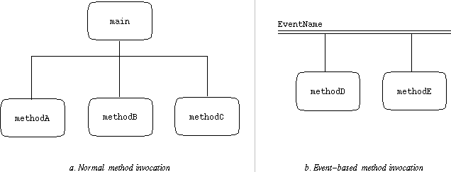
Figure 12: Event diagramming notation.
-
Figure 12a illustrates the normal mode of method invocation, where the
main method invokes methodA, methodB, and
methodC.
- Figure 12b illustrates the event-based invocation, where the event named "EventName" triggers the invocation of methodD and methodE.
-
Figure 12a illustrates the normal mode of method invocation, where the
main method invokes methodA, methodB, and
methodC.
- This notation is used in the example diagrams that follow.
-
Figure 13 shows excerpts from the Calendar Tool main function diagram related
to setting up the event handlers.
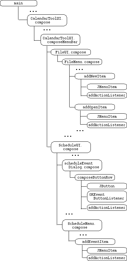
Figure 13: Setting up Calendar Tool event handlers.
-
Figure 14 shows excerpts from the Calendar Tool event-based invocation
hierarchy related to handling GUI events.
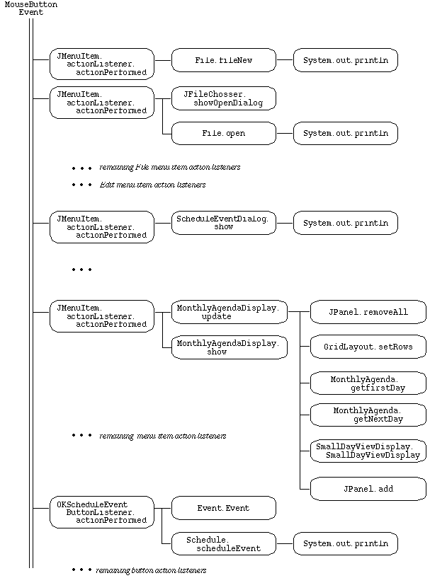
Figure 14: Responding to Calendar Tool GUI events.
-
These diagrams correspond to the following implementation source files:
- CalendarTool.java
- CalendarToolUI.java
- File.java
- FileUI.java
- FileMenu.java
- Schedule.java
- ScheduleUI.java
- ScheduleMenu.java
- ScheduledItem.java
- Event.java
- ScheduleEventDialog.java
- OKScheduleEventButtonListener.java
- MonthlyAgenda.java
- SmallDayView.java
- MonthlyAgendaDisplay.java
- SmallDayViewDisplay.java
- Lists.java
- AppointmentsListDisplay.java
-
The code in these files implements the design diagrams shown in the figures.
- We'll do a detailed walk-through of the code during class.