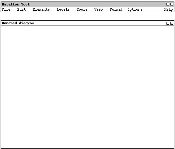
When the user initially invokes the stand-alone version of the Dataflow Tool,
the screen appears as shown in Figure 1.

Figure 1: Initial screen.
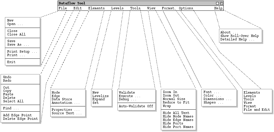
Figure 2 is an expansion of the command menus.

Figure 2: Expanded menus.
`File Save' saves the currently active canvas on the file from which it was opened, or on a new file if it was created from a new display. `File Save As' allows the current canvas to be saved on a different file from which it was opened or most recently saved upon. `File Save All' saves all currently open canvases.
`Print Setup' allows the user to set printing parameters for particular operating environments. `File Print' prints the contents of one or more active display windows, per the setup parameters. `File Exit' exits the Dataflow Tool, offering to save any modified calendars if necessary.
The Edit menu contains commands for manipulating DFD data during editing. `Edit Undo' undoes the most recently completed undoable command. `Edit Redo' redoes the most recently undone command. The undo and redo commands can be repeated successively to undo/redo a sequence of commands.
`Edit Cut' removes and copies the currently selected datum in the current display window. `Edit Copy' copies the currently selected datum without removing it. `Edit Paste' inserts the most recently cut or copied datum at the currently selected edit point in the current display. `Edit Delete' removes the currently selected datum without copying it. `Edit Select All' selects all editable data in the current display.
`Edit Find' performs a search for a text string. The search is performed in all open canvases. Successive invocations of search with an unchanged search string search for further occurrences of the string until all occurrences are found.
The last two commands on the edit menu allow the user to add and delete points to DFD edges. The edges themselves are added to the DFD with the `Elements->Edge' command.
The Elements menu has commands to add elements to a DFD in the current drawing canvas. The elements are a Node, Edge, Data Store, and free-form graphical annotation. The Properties command displays a dialog for editing properties of DFD elements. Source Text allows the user to edit the FMSL textual form of the DFD show in the drawing canvases.
The Levels menu has commands for managing different levels of a DFD. New creates a new empty level in a new canvas window. Levelize creates a new level out of a user-selected set of nodes in the current canvas. Expand opens the level canvas for a selected node. Set allows the user to define the expansion of an existing node to be another DFD canvas.
The Tools menu provides commands to operate on the DFD and its underlying FMSL specification. Validate checks the consistency and other properties of the DFD. Execute runs the DFD, providing visual tracing and other features. Debug provides commands to set breakpoints, examine runtime data, and other debugging functionality. Auto-Validate is a toggle that enables and disables incremental validation as the DFD is edited.
The View menu has commands to control the physical display of the DFD. The commands apply to the current canvas or all canvases, based on a user option setting. Zoom In and Zoom Out enlarge and decrease the size of the DFD display contents. Normal Size returns the display to its normal size. Reduce to Fit zooms the DFD to a size that fits entirely within the canvas window. Wrap changes the size of the display window so the DFD fits in it exactly, changing the zoom level only if the window size exceeds the available space on the computer screen.
The bottom five commands on the View menu are toggles that show and hide specific components of the DFD display. Show/Hide All Text operates on the text for all nodes, edges, and other elements of the display. Show/Hide Node Names operates only on the text of nodes names, leaving other text unaffected. Show/Hide Edge Names operates similarly on edge names only. Show/Hide Ports operates on the arrow-shaped icons for node ports. Show/Hide Port Names operates on port-name text only.
The Format menu has commands to control additional display details. Font allows the user to set the font for the text elements of the display. Color applies to the coloring of display elements. Dimensions allows the user to set the default dimensions of display elements. Shapes has commands to select the default shapes for nodes and edges.
Options commands allow the user to set various tool options. They are
organized into categories that correspond to the other command menus.