-
Milestones 3 and 4 writeup
-
SOP Volume 2: Requirements Testing
-
Java as an Abstract Modeling Language
- milestone 4 example
-
Covers material on SVN Basics handout and Week 4 lab notes.
-
Questions will be in terms of command-line interface to SVN.
- There will be no questions on SVN clients.
-
Everyone must attend all of the walkthroughs.
-
They will be held during lab on Monday through Friday, February 2 through 6,
per the following schedule:
Time Day Team 12:10 - 12:34 Mon 2 Feb DJ Cars 12:36 - 1:00 Mon 2 Feb TokenCSC 12:10 - 12:34 Wed 4 Feb Team 0 12:36 - 12:00 Wed 4 Feb Fire Breathing Rubber Duckies 12:10 - 12:34 Fri 6 Feb Node 12:36 - 1:00 Fri 6 Feb Team #1
-
Time your presentation to last 22 minutes, which will leave a bit of time for
questions.
-
The following are organizational guidelines for your presentation:
-
Present one title slide showing the name of your project and the members of
your team.
-
Present a few slides overviewing the basic project requirements (from Section 1
of the requirements document).
-
Present two slides showing the initial UI for the primary category of users,
and an expansion of the command menus (from Section 2.1 of the requirements).
-
If appropriate, show additional slides of alternate initial UIs for other major
categories of users (from Section 2.1).
-
Present additional screen-shot slides that show major features of your system
(from Sections 2.2 and beyond).
-
Prepare additional explanatory slides to aid the presentation.
-
You do not necessarily need a lot of explanatory slides -- you may choose to
discuss system features mostly orally.
- If you do have explanatory slides, they should have only major points, in large text font (at least 24 points).
-
You do not necessarily need a lot of explanatory slides -- you may choose to
discuss system features mostly orally.
-
Present one title slide showing the name of your project and the members of
your team.
-
You may make your presentation electronically (e.g., Acrobat, PowerPoint, HTML)
or on overhead transparencies.
- If you prepare your presentation in HTML, please organize it into slides, so as to avoid the distraction of jumping around in a browser during the presentation.
-
In what might be called a traditional view of the software process, testing is
seen as the last step, following implementation.
-
In this view, the program code itself is the only artifact that is subject to
formal testing.
-
While code testing is critically important for quality software, the code is
not the only artifact that should be tested.
- In fact, all of the other major software process artifacts can be tested formally -- the requirements, the specification, and the design.
-
In this view, the program code itself is the only artifact that is subject to
formal testing.
-
Figure 1 compares the position of testing as the final step of the process
versus a pervasive step.
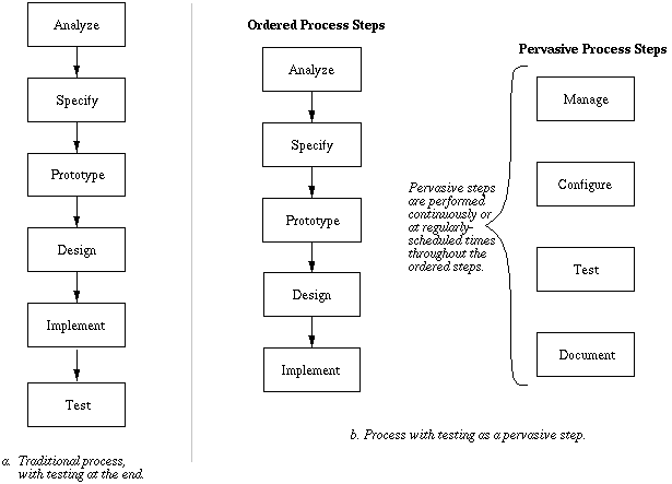
Figure 1: Two views of testing in the software process.
-
As discussed in Lecture Notes Week 1, pervasive steps run continuously
throughout the development process, or at regularly-scheduled intervals.
- In addition to testing, the other pervasive steps deal with management, configuration, and documentation.
-
As discussed in Lecture Notes Week 1, pervasive steps run continuously
throughout the development process, or at regularly-scheduled intervals.
-
There are three types of testing that are performed during different stages of
the software process.
-
Inspection testing entails systematic human inspection of all levels
of software artifact, from requirements through implementation.
-
Functional testing is performed by programmers on the executable code
as it is developed.
- Acceptance testing is performed by end users on the released product.
-
Inspection testing entails systematic human inspection of all levels
of software artifact, from requirements through implementation.
-
Testing with walkthroughs and reviews.
-
The purpose is the same as walkthroughs and reviews conducted during the
development of just about any kind of product.
-
Namely, we want to assure that what is being developed is on track and meets
customer needs.
-
Walkthroughs and reviews are an important means to "debug" the requirements.
-
Public reviews can be held at specific milestones during the course of
requirements gathering and analysis.
-
Limited members of the technical staff hold detailed walkthroughs to refine
requirements specifications.
-
Such walkthroughs are particularly important in the process of requirements
analysis since such a wide range of people are potentially involved.
-
In 308, intra-group walkthroughs are conducted during our weekly meetings.
- In addition, each group will gives two oral reviews to the rest of the class during in the quarter; first is in week 5 as scheduled above.
-
The purpose is the same as walkthroughs and reviews conducted during the
development of just about any kind of product.
-
Formal inspection testing.
-
Starting in week 4, the functional requirements will be formally inspected by a
duly appointed inspection test engineer.
-
During weeks 4 through 11, each group member will have a one-week assignment as
the official inspection tester (see milestone 3 writeup for exact schedule,
since it varies based on team size).
- Details are in the handout entitled "Standard Operating Procedures, Volume 2: Requirements Testing"
-
Starting in week 4, the functional requirements will be formally inspected by a
duly appointed inspection test engineer.
-
Model building as a means of concept testing.
-
A common practice among engineers is to build a model of a proposed engineered
artifact, to see if the high-level ideas about the artifact are sound.
- For CSC 308, model building is done during the next ordered step of the software process after requirements analysis -- specification.
-
A common practice among engineers is to build a model of a proposed engineered
artifact, to see if the high-level ideas about the artifact are sound.
-
The goal is to formalize the user-oriented functional requirements, so that:
-
the requirements are complete and consistent;
- the requirements are clear and unambiguous for the system design and implementation team.
-
the requirements are complete and consistent;
- While fully formal modeling of software is not (yet) practiced as widely as for other forms of engineered artifacts, the utility of formal software models is substantial. Semi-formal modeling is gaining wider acceptance in the SE world.
-
Candidates include:
-
"Firmed up" English and pictures -- understandable but imprecise.
-
Semi-formal requirements specification languages -- helpful for high-level
modeling, but not precise enough to ensure a complete and consistent
specification.
-
Graphical notations -- helpful to clarify some aspects of a formal model, but
not generally adequate for a complete specification.
- Fully formal textual notations, including mathematics -- these remove all imprecision but are very demanding to use and understand.
-
"Firmed up" English and pictures -- understandable but imprecise.
-
Alas, "demanding to use and understand" is an attribute of many formal
engineering notations.
-
Building and analyzing formal models is an important part of what engineers do
to earn their keep.
- Without a formal model, we run the very substantial risk of not fully understanding the system we want to build, and as a result building a faulty system.
-
Building and analyzing formal models is an important part of what engineers do
to earn their keep.
-
Why a formal language?
-
Remove the imprecision and ambiguity of normal English prose.
-
Avoid misunderstanding among analysts and potential users --
consistency.
-
Provide a means to identify when the requirements analysis process is finished
-- completeness.
- Provide some quantifiable measures by which to judge if a delivered system actually meets the requirements -- verifiability.
-
Remove the imprecision and ambiguity of normal English prose.
-
In 308, we will go all the way down to formal mathematical logic.
-
We will do so in a sequence of steps from informal, to semi-formal, to fully
formal.
-
Each step requires more work and more specialized knowledge.
-
In the real world, different participants in the analysis process will have
different technical backgrounds.
-
Therefore, not all analysts will be involved with the most formal aspects of
the document.
- It is ultimately the job of the systems analyst to take input from all other analysts and produce a fully formal result.
-
Therefore, not all analysts will be involved with the most formal aspects of
the document.
-
Formality is particularly important in a growing number of "safety-critical"
applications, such as avionics and medical systems, among others.
-
General rule -- the more important it is to prove that a computer system works
properly, the more formally must it be specified.
- Formal specification can be used in other areas that do not strictly involve safety, such as verifiably secure information processing system for financial transactions.
-
General rule -- the more important it is to prove that a computer system works
properly, the more formally must it be specified.
-
The first step in formalizing user-oriented requirements is to build a
requirements model.
-
The model is a more abstract representation of the requirements, written in a
more formal language than English prose and pictures.
-
The objective in building the model is to depict the structure and operational
behavior of a proposed system accurately and precisely.
-
Elements of the requirements model are the following:
-
The definition of objects upon which the system operates.
-
The definition of operations that the system performs.
-
The definition of object and operation attributes.
-
The definition of relationships between objects and operations.
-
Statements of fact about objects and operations, which statements can
be validated to be true or false.
- Explanatory remarks that aid in human understanding of the model.
-
The definition of objects upon which the system operates.
-
The formal language we will use in 308 is Java, with modifications to make it
suitable as an abstract specification language.
-
An overview is presented in the handout entitled
"Java as an Abstract Modeling Language".
-
Here is a summary of using Java as abstract modeling language:
-
Objects are modeled as fully abstract Java classes or enums; no concrete
classes, no interfaces.
-
Operations are modeled as method signatures; no method implementations.
-
Object attributes are modeled as Java annotations.
-
Object relationships are
-
has-a, which is modeled as data fields
- is-a, which is modeled as inheritance using extends
-
has-a, which is modeled as data fields
-
Statements of fact are modeled with JML assertions (more on this in coming
weeks)
-
The following Java features are not used in an abstract model:
-
executable code
-
information hiding with public, private, or
protected
-
exceptions
-
library data structures except Collection
-
primitive types except int, double, and boolean
- any other Java feature not explicitly mentioned above
-
executable code
-
Objects are modeled as fully abstract Java classes or enums; no concrete
classes, no interfaces.
-
In our scenario style of requirements analysis, the requirements model is
derived from the pictures of the user interface and the accompanying textual
narrative.
-
The following heuristics can be used to derive an initial set of objects and
operations from a graphical user interface:
-
Function buttons and menu items generally correspond to operations.
-
Data-entry screens and output screens generally correspond to objects.
-
More specifically, data-entry dialogs that appear in response to invoking an
operation generally correspond to the input object(s) for the invoked
operation.
-
Output reporting screens that appear in response to confirming an input dialog
(E.g., with an "OK" button) generally correspond to the output object(s) for
the confirmed operation.
-
Interface elements that allow entry of a single number, string, or boolean
value correspond to primitive types.
- The hierarchical structure of objects is generally displayed in the interface by nested or cascading windows and boxes, with primitive elements at the lowest level of nesting.
-
Function buttons and menu items generally correspond to operations.
- Specific details of object and operation attributes are derived from the scenario narrative that accompanies the interface pictures.
-
To illustrate the derivation of a requirements model, we'll apply the preceding
basic heuristics to Calendar Tool example.
- Complete details of the initial modeling for the Calendar Tool are in the specification directory of Milestone 4 example.
-
Here is the top-level Schedule command menu from the Calendar Tool:

-
Applying the first heuristic (buttons and menus indicate operations), we can
identify the following four operations from the Schedule menu:
void scheduleAppointment();
void scheduleMeeting();
void scheduleTask();
void scheduleEvent();
-
We have not yet identified the following aspects of these operations:
-
What class they go in.
-
What parameter(s) they take.
- What return value, if any, they produce.
-
What class they go in.
-
Linguistically, operation names should always be verbs or verb phrases.
-
Depending on how the user commands are structured, we can use different
combinations of interface element names to derive meaningful operation names.
-
In this case, which is reasonably typical, we've concatenated a menu name with
the name of each menu item to derive the operation names.
-
An important point is to have traceability between the terminology used in the
user interface and the corresponding model.
-
In fact, the derivation of model names can help point out flaws or
inconsistencies in the interface scenarios.
-
If it is difficult to derive a simple and meaningful name for an operation from
the interface, this is a sign that the interface naming might well be improved.
-
This is an instance of a recurring principle in requirements analysis and
modeling -- "form follows function".
- That is, a well-defined interface scenario leads to a well-defined model, and vice versa.
-
In fact, the derivation of model names can help point out flaws or
inconsistencies in the interface scenarios.
-
Depending on how the user commands are structured, we can use different
combinations of interface element names to derive meaningful operation names.
-
From the second heuristic (data screens are objects), we can identify as
objects each of the data-entry screens that appear in response to the user
selecting one of the Schedule menu operations.
-
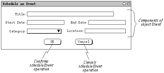
To start with a simple example first, let us consider the derivation of the
Event object, from the following interface picture:
-
Applying heuristics 5 and 6, we can derive the following object definitions:
class Event {
    String title;
    Date startDate
    Date endDate
    Category category
    String location;
}
class Date { /* ... */ }
class Category { /* ... */ }
with an annotated version of the derivation looking like this: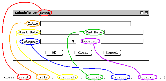
-
In these definitions, we've done the following initial data analysis:
-
The title and location fields are primitive string type.
- The other data fields are defined as object types that we've named, but not yet fully defined.
-
The title and location fields are primitive string type.
-
As discussed in the
"Java as Modeling Language" handout
there are only a few Java forms used to model data
-
Table 1 summarizes these, along with the common interface forms.
Java Form Meaning Common Interface Form int numeric integer string editor for numbers; numeric slider bar or dial double numeric real number same as integer String free-form string value string editor or combo box boolean true/false value string editor for true/false value; on/off button class data fields components of the class box containing other types enum literals one of a set of possibilities radio buttons; fixed-length listing of selections Collection zero or more components of the same type variable-length listing of data values or selections Method the type of an operation push button or menu item Table 1: Java Modeling Forms.
-
These are constructs you should be familiar with in Java.
- The table notes common interface forms for each of the basic object types.
-
An examination of the narrative for the event dialog, indicates that the
Title and Location components of an event are free-form
strings, hence their definition as String types.
-
Java's String type is used to model a any free-form text string that
the user may type.
-
In Milestone 4, the details of date formats has not yet been worked out.
-
Given this, we'll leave the definitions of the Date class to be
resolved later.
-
I.e., we'll leave the definitions as
class Date { /* ... */ }
-
Given this, we'll leave the definitions of the Date class to be
resolved later.
-
The user interface displays the Category as a list of selections.
-
This might lead us to consider modeling the Category component as a
list of form
class Category { String* list; } -
However, a more careful analysis of the requirements shows that for a given
event, the Category component is only one of a set of possibilities.
-
Hence, the Category component would not be a list, but rather just a
primitive String.
-
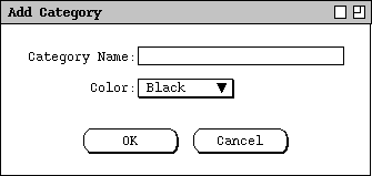
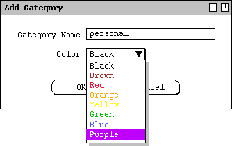
Further analysis of the requirements shows that a category is not just a plain
string, since each category has an explicitly selected color, as shown in the
add-category dialog:
-
Hence, the most accurate definition of Category is
class Category { String name; Color color; } -
A subsequent screen shot in the scenarios shows that the Color
component is one of a fixed set of selections:
-
Accordingly, we can model Color as follows:
enum Color {
    Black, Brown, Red, Orange, Yellow or Green, Blue, Purple;
}
-
This might lead us to consider modeling the Category component as a
list of form
-
The preceding analysis for deriving objects is typical in requirements
modeling.
-
First we derive initial object definitions from the UI pictures.
-
Then we refine the definitions based on the scenario narrative.
- We continue to refine until all objects are defined in terms of primitives, or we've decided to defer complete definition of model data until more requirements have been completed.
-
First we derive initial object definitions from the UI pictures.
-
The key step in refining an operation is determining what object class it
belongs in.
-
This will clarify what object is operated on.
-
In the case of the four scheduling operations, an analysis of the requirements
leads us to understand that these operations work on a Calendar
object.
-
Hence, we have the definition
class Calendar { void scheduleAppointment(); void scheduleMeeting(); void scheduleTask(); void scheduleEvent(); } -
Using heuristic 3 (data-entry dialogs are input objects), we refine the four
scheduling operations as follows:
class Calendar { void scheduleAppointment(Appointment); void scheduleMeeting(Meeting); void scheduleTask(Task); void scheduleEvent(Event); } -
Since we want all of our models to compile with the Java compiler, we need to
clarify that the preceding definition is intended to be an abstract model.
-
Abstract in this context means, among other things, that we leave out all
operational code from the model.
- Hence to compile in Java we must declare all of the methods to be abstract, as well as the class that contains these methods.
-
Abstract in this context means, among other things, that we leave out all
operational code from the model.
-
So, here is the compilable definition of the modeled Calendar object, along
with its operations:
abstract class Calendar {
    abstract void scheduleAppointment(Appointment);
    abstract void scheduleMeeting(Meeting);
    abstract void scheduleTask(Task);
    abstract void scheduleEvent(Event);
}
-
A key aspect of data modeling is the identification of collection
objects.
-
Abstractly, a collection contains zero or more objects of a particular type.
-
In terms of requirements scenarios, collections can be identified by language
that describes objects with multiple entries, and operations that add entries
to the collection.
-
For example, in Section 2.2 of the Calendar Tool scenarios, the following kind
of language helps identify the calendar as a collection of appointments:
"After scheduling and confirming an appointment, the appointment data are entered in an online working copy of the user's calendar."
-
With Java as a modeling language, we will use the Collection interface
to model abstract collections, as in this definition of Calendar:
abstract class Calendar { abstract void scheduleAppointment(Appointment); abstract void scheduleMeeting(Meeting); abstract void scheduleTask(Task); abstract void scheduleEvent(Event);Collection<Appointment> data; }
-
Representing a Calendar as a collection of Appointments is in fact an
over-simplification of a Calendar, since calendars can contain
meetings, tasks and events, as well as appointments.
-
We'll address this issue soon, by defining a parent class for these four types
of scheduled items, and representing Calendar data thusly:
Collection<ScheduledItem> data; -
Another way to identify collections in requirements scenarios is by the pattern
of operations that are used on collections.
-
The operations are additive, destructive, modifying,
and selective.
-
In more common terms, these are operations to add, delete, edit, and find items
in a collection.
- In upcoming notes, we'll consider this to be a formal specification pattern.
-
The operations are additive, destructive, modifying,
and selective.
-
A significant number of objects and operations will ultimately be derived from
the calendar View commands.
-
As an initial example, consider in Figure 2 the monthly view that is displayed
in response to the user selecting the Month item in the View
menu.
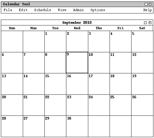
Figure 2: Monthly calendar view.
-
From this we can derive the following objects:
import java.util.Collection;

/**
 * A MonthlyAgenda contains a small daily view for each day of the month,
 * organized in the fashion typical in paper calendars.
 */
class MonthlyAgenda {
    FullMonthName name;
    DayOfTheWeek firstDay;
    int numberOfDays;
    Collection<SmallDayView> items;
}

class FullMonthName {
    String month;
    int year;
}

enum DayOfTheWeek { Sun, Mon, Tue, Wed, Thu, Fri, Sat }

/**
 * A SmallDayView has the number of the date and a list of zero or more short
 * item descriptions.
 */
class SmallDayView {
    int DateNumber;
    Collection<BriefItemDescription> items;
}

class BriefItemDescription {
    String title;
    Time startTime;
    Duration duration;
    Category category;
}

class Time { /* ... */ }
class Duration { /* ... */ }
class Category { /* ... */ }
-
The Calendar Tool will provide some interesting examples where a model can be
derived in a number of different ways.
-
For example, should the Calendar itself be modeled as a collection of scheduled
items or as a collection of years?
-
Should dates be modeled as simple strings or a composite objects?
- Which of these is the "correct" or "most accurate" way to model?
-
For example, should the Calendar itself be modeled as a collection of scheduled
items or as a collection of years?
-
The general answer to such questions is that we strive to model objects and
operations as perceived by the end user.
-
Our single criterion for model correctness and accuracy is based on how well we
represent objects and operations in terms of what the user thinks.
-
What we definitely do not want to do is model things in terms of efficient
computer data structures.
- We will discuss these requirements modeling ideas more in upcoming lectures.
-
Our single criterion for model correctness and accuracy is based on how well we
represent objects and operations in terms of what the user thinks.